
Quick Start Manual


Installation
24
FS752TP Smart Switch
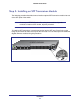
Step 5: Installing an SFP Transceiver Module
The following procedure describes how to install an optional SFP transceiver module into one
of the SFP ports of the switch.
Note: Contact your NETGEAR sales office to buy these modules. If you do
not want to install an SFP module, skip this procedure.
To install an SFP transceiver, insert the transceiver into the SFP port. Press firmly on the
flange of the module to seat it securely into the connector. You can install up to two additional
Gigabit Ethernet modules using this procedure.
Ports 1-48, Link/Act Mode — Green=Link at 100M, Yellow=Link at 10M Blink=ACT
Ports 49-52 Link/Act Mode — Green=1G, Yellow=10/100M Blink=ACT
Power
Reset
Select
Fan
PoE Max
LED Mode
Yellow=PoE
Green=Link/ACT
Facto ry
Defaults
1
2
3
4
5
6
7
8
9
10
11 13 15 17 19 21
12 2214 16 18 20
23 25 27 29 31 33
24 3426 28 30 32
35 37 39 41 43 45 47
36 38 40 42 44 46 48 52
FS752TP
50F 50T
49F 49T
Combo Ports
51
P
orts 49-52 Lin
k
/Act
Mode
e
e
—
—
—
—
—
—
—
—
—
—
Green=1G
Green 1
Green=
Green=1G,
Green=1
Green=1G,
Green=1
ee
en=1G,
en=1G
een=1G
een=1G
en=1G,
een 1
en=1G
Green=1G
1G
een=1G,
G
G,
Green 1G
G
G,
=1G,
Green=1
e
en
=1
n
G,
e
G
G,
Y
Y
Yellow=
Yellow=1
Yellow=
Yellow=
Yellow=10
Yellow=1
0
0
Y
Y
Yellow=
Yellow=
ow 1
w
w
Y
l
ow=
w
w
=
w=
1
10
0
0
o
=
1
10
0
1
10
/
/
1
1
100
0
0
00
0
M
0M
/100M Bli
/
1
1
0
0
0
0M
/100
/
/100
n
k
=ACT
22
23
2
5
27
29
31
33
24
34
26
28
30
32
35
37
39
41
43
45
47
36
38
40
42
44
46
48
5
2
F
S
7
5
2T
P
5
0
F
50
T
49
F
49
T
Combo Po
bo Po
Po
o P
Po
Po
o
Po
P
o Po
o
o
o
P
P
o
o
o
o
P
P
P
Po
o
Po
o
o
o
t
t
t
rts
r
r
r
ts
s
r
r
rts
rt
rt
ts
rts
r
rt
ts
s
r
r
rt
t
rts
s
51