
User Manual
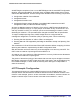
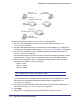
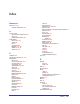
Table Of Contents
- FS728TP Smart Switch
- Table of Contents
- 1. Getting Started
- Getting Started with the FS728TP Smart Switch
- Switch Management Interface
- Connecting the Switch to the Network
- Switch Discovery in a Network with a DHCP Server
- Switch Discovery in a Network without a DHCP Server
- Configuring the Network Settings on the Administrative System
- Web Access
- Smart Control Center Utilities
- Understanding the User Interfaces
- Interface Naming Convention
- 2. Configuring System Information
- 3. Configuring Switching Information
- 4. Configuring Quality of Service
- 5. Managing Device Security
- 6. Monitoring the System
- 7. Maintenance
- 8. Help
- A. Hardware Specifications and Default Values
- B. Configuration Examples
- C. Notification of Compliance
- Index

252 | Appendix B: Configuration Examples
FS728TP Smart Switch Software Administration Manual
Perform the following procedures on each switch to configure MSTP:
1. Use the VLAN Configuration screen to create VLANs 300 and 500 (see VLAN
Configuration on page 82).
2. Use the VLAN Membership screen to include ports e1–e8 as tagged (T) or untagged (U)
members of VLAN 300 and VLAN 500 (see
VLAN Membership Configuration on page 83).
3. From the STP Configuration screen, enable the Spanning Tree State option (see STP
Switch Configuration on page 91).
Use the default values for the rest of the STP configuration settings. By default, the STP
Operation Mode is MSTP and the Configuration Name is the switch MAC address.
4. From the CST Configuration screen, set the Bridge Priority value for each of the three
switches to force Switch 1 to be the root bridge:
• Switch 1: 4096
• Switch 2: 12288
• Switch 3: 20480
Note: Bridge priority values are multiples of 4096.
If you do not specify a root bridge and all switches have the same Bridge Priority value,
the switch with the lowest MAC address is elected as the root bridge (see
CST
Configuration on page 93).
5. From the CST Port Configuration screen, select ports e1–e8 and select Enable from the
STP Status menu (see
CST Port Configuration on page 95).
6. Click Apply.
7. Select ports e1–e5 (edge ports), and select Enable from the Fast Link menu.
Ports e1-e5
Switch 1
Connected to Hosts
Root Bridge
Switch 2
Switch 3
Ports e1-e5
Connected to Hosts
Ports e1-e5
Connected to Hosts
Ports e6-e8
Connected to Switch 2 and 3
Ports e6-e8
Connected to Switch 1 and 2