
User Manual
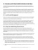
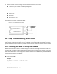

Table Of Contents
- 1. Introduction
- 2. Quick Startup
- 3. Console and Telnet Administration Interface
- 4. Command Line Interface Structure and Mode-based CLI
- 5. Switching Commands
- 5.1. System Information and Statistics Commands
- 5.1.1. show arp
- 5.1.2. show calendar
- 5.1.3. show process cpu
- 5.1.4. show process cpu threshold
- 5.1.5. show eventlog
- 5.1.6. show running-config
- 5.1.7. show sysinfo
- 5.1.8. POST Diagnostic Commands
- 5.1.9. show system
- 5.1.10. show tech-support
- 5.1.11. show hardware
- 5.1.12. show version
- 5.1.13. show logingsessin
- 5.1.14. show command filter
- 5.1.15. show transceiver device
- 5.1.16. show transceiver interface
- 5.1.17. show process memory
- 5.1.18. show process app-list
- 5.1.19. show process app-resource-list
- 5.1.20. show process proc-list
- 5.1.21. show environment
- 5.1.22. show configuration files
- 5.1.23. process cpu threshold
- 5.1.24. memory free low-watermark processor
- 5.1.25. show supported cardtype
- 5.1.26. show supported cardtype
- 5.1.27. pager
- 5.1.28. show pager
- 5.2. Device Configuration Commands
- 5.2.1. Interface commands
- 5.2.1.1. show interface status
- 5.2.1.1.1. show interface status
- 5.2.1.1.2. show interface status
- 5.2.1.1.3. show interface status err-disabled
- 5.2.1.1.4. show interface status loopback <0-63>
- 5.2.1.1.5. show interface status port-channel <1-64>
- 5.2.1.1.6. show interface status tunnel <0-7>
- 5.2.1.1.7. show interface status vlan <1-4093>
- 5.2.1.2. show interface counters
- 5.2.1.3. show interface dampening
- 5.2.1.4. show interface loopback
- 5.2.1.5. show interface port-channel
- 5.2.1.6. show interface port-mode
- 5.2.1.7. show interface priority flow control
- 5.2.1.8. show interface switch
- 5.2.1.9. show interface switchport
- 5.2.1.10. show interface tunnel
- 5.2.1.11. show interface description
- 5.2.1.12. show interface fec
- 5.2.1.13. show interface advertise
- 5.2.1.14. Interface configuraton commands
- 5.2.1.15. show port status all
- 5.2.1.16. Show flowcontrol
- 5.2.1.1. show interface status
- 5.2.2. Show BMC Commands
- 5.2.3. L2 MAC Address and Multicast Forwarding Database Tables
- 5.2.3.1. show mac-addr-table
- 5.2.3.2. show mac-addr-table count
- 5.2.3.3. show mac-addr-table interface
- 5.2.3.4. show mac-address-table igmpsnooping
- 5.2.3.5. show mac-address-table multicast
- 5.2.3.6. show mac-address-table status
- 5.2.3.7. show mac-addr-table agetime
- 5.2.3.8. mac-addr-table aging-time
- 5.2.3.9. no mac-addr-table aging-time
- 5.2.3.10. clear mac-addr-table dynamic
- 5.2.4. VLAN Commands
- 5.2.4.1. vlan database
- 5.2.4.2. vlan
- 5.2.4.3. no vlan
- 5.2.4.4. vlan makestatic
- 5.2.4.5. vlan name
- 5.2.4.6. no vlan name
- 5.2.4.7. switchport acceptable-frame-types
- 5.2.4.8. no switchport acceptable-frame-types
- 5.2.4.9. switchport acceptbale-frame-type all
- 5.2.4.10. no switchport acceptable-frame-types all
- 5.2.4.11. switchport ingress-filtering
- 5.2.4.12. no switchport ingress-filtering
- 5.2.4.13. switchport ingress-filtering all
- 5.2.4.14. no switchport ingress-filtering all
- 5.2.4.15. switchport native vlan
- 5.2.4.16. no switchport native vlan
- 5.2.4.17. switchport native vlan all
- 5.2.4.18. no switchport native vlan all
- 5.2.4.19. switchport allowed vlan
- 5.2.4.20. switchport allowed vlan all
- 5.2.4.21. switchport tagging
- 5.2.4.22. no switchport tagging
- 5.2.4.23. switchport tagging all
- 5.2.4.24. no switchport tagging all
- 5.2.4.25. show vlan
- 5.2.4.26. show vlan id
- 5.2.4.27. show vlan internal usage
- 5.2.4.28. show interface switchport
- 5.2.4.29. show vlan private-vlan
- 5.2.4.30. show vlan remote-span
- 5.2.5. Private VLAN Commands
- 5.2.6. Switch Ports
- 5.2.6.1. switchport mode
- 5.2.6.2. no switchport mode
- 5.2.6.3. switchport trunk allowed vlan
- 5.2.6.4. no switchport trunk allowed vlan
- 5.2.6.5. switchport trunk native vlan
- 5.2.6.6. no switchport trunk native vlan
- 5.2.6.7. switchport access vlan
- 5.2.6.8. no switchport access vlan
- 5.2.6.9. show interfaces switchport
- 5.2.7. Double VLAN Commands
- 5.2.8. IGMP snooping commands
- 5.2.8.1. ip igmp snooping
- 5.2.8.2. no ip igmp snooping
- 5.2.8.3. clear igmp snooping
- 5.2.8.4. ip igmp snooping interfacemode
- 5.2.8.5. no ip igmp snooping interfacemode
- 5.2.8.6. ip igmp snooping interfacemode all
- 5.2.8.7. no ip igmp snooping interfacemode all
- 5.2.8.8. ip igmp snooping fast-leave
- 5.2.8.9. no ip igmp snooping fast-leave
- 5.2.8.10. ip igmp snooping groupmembershipinterval
- 5.2.8.11. no ip igmp snooping groupmembershipinterval
- 5.2.8.12. ip igmp snooping mcrtrexpiretime
- 5.2.8.13. no ip igmp snooping mcrtrexpiretime
- 5.2.8.14. ip igmp snooping mrouter
- 5.2.8.15. no ip igmp snooping mrouter
- 5.2.8.16. set igmp
- 5.2.8.17. no set igmp
- 5.2.8.18. set igmp fast-leave
- 5.2.8.19. no set igmp fast-leave
- 5.2.8.20. set igmp groupmembership-interval
- 5.2.8.21. no set igmp groupmembership-interval
- 5.2.8.22. set igmp maxresponse
- 5.2.8.23. no set igmp maxresponse
- 5.2.8.24. set igmp mcrtrexpiretime
- 5.2.8.25. no set igmp mcrtrexpiretime
- 5.2.8.26. set igmp report-suppression
- 5.2.8.27. no set igmp report-suppression
- 5.2.8.28. set snoop-vlan-block
- 5.2.8.29. no set snoop-vlan-block
- 5.2.8.30. ip igmp snooping static
- 5.2.8.31. no ip igmp snooping static
- 5.2.8.32. ip igmp snooping router-alert-check
- 5.2.8.33. no ip igmp snooping router-alert-check
- 5.2.8.34. show ip igmp snooping
- 5.2.8.35. show ip igmp snooping mrouter interface
- 5.2.8.36. show ip igmp snooping mrouter vlan
- 5.2.8.37. show ip igmp snooping static
- 5.2.8.38. show mac-address-table igmpsnooping
- 5.2.8.39. show ip igmp snooping ssm entries
- 5.2.8.40. show ip igmp snooping ssm groups
- 5.2.8.41. show ip igmp snooping ssm stats
- 5.2.8.42. ip igmp snooping maxresponse
- 5.2.8.43. no ip igmp snooping maxresponse
- 5.2.9. IGMP snooping querier commands
- 5.2.9.1. ip igmp snooping querier
- 5.2.9.2. no ip igmp snooping querier
- 5.2.9.3. ip igmp snooping querier address
- 5.2.9.4. no ip igmp snooping querier address
- 5.2.9.5. ip igmp snooping querier query-interval
- 5.2.9.6. no ip igmp snooping querier query-interval
- 5.2.9.7. ip igmp snooping querier querier-expiry-interval
- 5.2.9.8. no ip igmp snooping querier querier-expiry-interval
- 5.2.9.9. ip igmp snooping querier version
- 5.2.9.10. no ip igmp snooping querier version
- 5.2.9.11. ip igmp snooping querier vlan
- 5.2.9.12. no ip igmp snooping querier vlan
- 5.2.9.13. ip igmp snooping querier vlan address
- 5.2.9.14. no ip igmp snooping querier vlan address
- 5.2.9.15. ip igmp snooping querier vlan election participate
- 5.2.9.16. no ip igmp snooping querier vlan election participate
- 5.2.9.17. show ip igmp snooping querier
- 5.2.9.18. show ip igmp snooping querier vlan
- 5.2.9.19. show ip igmp snooping querier detail
- 5.2.10. MLD Snooping Commands
- 5.2.10.1. show ipv6 mld snooping
- 5.2.10.2. show ipv6 mld snooping mrouter interface
- 5.2.10.3. show ipv6 mld snooping mrouter vlan
- 5.2.10.4. show ipv6 mld snooping static
- 5.2.10.5. show mac-address-table mldsnooping
- 5.2.10.6. show ipv6 mld snooping ssm entries
- 5.2.10.7. show ipv6 mld snooping ssm groups
- 5.2.10.8. show ipv6 mld snooping ssm stats
- 5.2.10.9. ipv6 mld snooping
- 5.2.10.10. no ipv6 mld snooping
- 5.2.10.11. clear mld snooping
- 5.2.10.12. ipv6 mld snooping interfacemode
- 5.2.10.13. no ipv6 mld snooping interfacemode
- 5.2.10.14. ipv6 mld snooping interfacemode all
- 5.2.10.15. no ipv6 mld snooping interfacemode all
- 5.2.10.16. ipv6 mld snooping fast-leave
- 5.2.10.17. no ipv6 mld snooping fast-leave
- 5.2.10.18. ipv6 mld snooping groupmembershipinterval
- 5.2.10.19. no ipv6 mld snooping groupmembershipinterval
- 5.2.10.20. ipv6 mld snooping mcrtrexpiretime
- 5.2.10.21. no ipv6 mld snooping mcrtrexpiretime
- 5.2.10.22. ipv6 mld snooping mrouter
- 5.2.10.23. no ipv6 mld snooping mrouter
- 5.2.10.24. ipv6 mld snooping static
- 5.2.10.25. no ipv6 mld snooping static
- 5.2.10.26. set mld
- 5.2.10.27. no set mld
- 5.2.10.28. set mld fast-leave
- 5.2.10.29. no set mld fast-leave
- 5.2.10.30. set mld groupmembership-interval
- 5.2.10.31. no set mld groupmembership-interval
- 5.2.10.32. set mld maxresponse
- 5.2.10.33. no set mld maxresponse
- 5.2.10.34. set mld mcrtrexpiretime
- 5.2.10.35. no set mld mcrtrexpiretime
- 5.2.11. MLD Snooping Querier Commands
- 5.2.11.1. show ipv6 mld snooing querier
- 5.2.11.2. show ipv6 mld snooping querier vlan
- 5.2.11.3. show ipv6 mld snooping querier detail
- 5.2.11.4. ipv6 mld snooping querier
- 5.2.11.5. no ipv6 mld snooping querier
- 5.2.11.6. ipv6 mld snooping querier address
- 5.2.11.7. no ipv6 mld snooping querier address
- 5.2.11.8. ipv6 mld snooping querier query-interval
- 5.2.11.9. no ipv6 mld snooping querier querier-interval
- 5.2.11.10. ipv6 mld snooping querier querier-expiry-interval
- 5.2.11.11. no ipv6 mld snooping querier querier-expiry-interval
- 5.2.11.12. ipv6 mld snooping querier vlan
- 5.2.11.13. no ipv6 mld snooping querier vlan
- 5.2.11.14. ipv6 mld snooping querier vlan address
- 5.2.11.15. no ipv6 mld snooping querier vlan address
- 5.2.11.16. ipv6 mld snooping querier vlan election participate
- 5.2.11.17. no ipv6 mld snooping querier vlan election participate
- 5.2.12. Port-Channel/LAG (802.3ad) Commands
- 5.2.12.1. show interface port-channel brief
- 5.2.12.2. show interface port-channel
- 5.2.12.3. show interface port-channel system priority
- 5.2.12.4. show lacp actor
- 5.2.12.5. show lacp interface
- 5.2.12.6. interface port-channel
- 5.2.12.7. staticcapability
- 5.2.12.8. no staticcapability
- 5.2.12.9. port-channel linktrap
- 5.2.12.10. no port-channel linktrap
- 5.2.12.11. port-channel load-balance
- 5.2.12.12. no port-channel load-balance
- 5.2.12.13. load-balance
- 5.2.12.14. no load-balance
- 5.2.12.15. port-channel system priority
- 5.2.12.16. no port-channel system priorty
- 5.2.12.17. lacp
- 5.2.12.18. no lacp
- 5.2.12.19. lacp all
- 5.2.12.20. no lacp
- 5.2.12.21. lacp admin key
- 5.2.12.22. no lacp admin key
- 5.2.12.23. lacp actor admin key
- 5.2.12.24. no lacp actor admin key
- 5.2.12.25. lacp actor admin state
- 5.2.12.26. no lacp actor admin state
- 5.2.12.27. lacp actor port priority
- 5.2.12.28. no lacp actor port priority
- 5.2.12.29. min-links
- 5.2.12.30. no min-links
- 5.2.12.31. lacp fallback
- 5.2.12.32. no lacp fallback
- 5.2.12.33. lacp fallback timeout
- 5.2.12.34. no lacp fallback timeout
- 5.2.12.35. channel-group
- 5.2.12.36. no channel-group
- 5.2.12.37. delete-channel-group
- 5.2.12.38. port lacpmode enable all
- 5.2.12.39. port lacptimeout
- 5.2.13. Storm Control
- 5.2.13.1. show storm-control
- 5.2.13.2. storm-control Configuration
- 5.2.13.3. storm-control broadcast
- 5.2.13.4. no storm-control broadcast
- 5.2.13.5. storm-control broadcast action
- 5.2.13.6. no storm-control broadcast action
- 5.2.13.7. storm-control broadcast rate
- 5.2.13.8. no storm-control broadcast rate
- 5.2.13.9. storm-control broadcast level
- 5.2.13.10. no storm-control broadcast level
- 5.2.13.11. storm-control multicast
- 5.2.13.12. no storm-control multicast
- 5.2.13.13. storm-control multicast action
- 5.2.13.14. no storm-control multicast action
- 5.2.13.15. storm-control multicast level
- 5.2.13.16. no storm-control multicast level
- 5.2.13.17. storm-control multicast rate
- 5.2.13.18. no storm-control multicast rate
- 5.2.13.19. storm-control unicast
- 5.2.13.20. no storm-control unicast
- 5.2.13.21. storm-control unicast action
- 5.2.13.22. no storm-control unicast action
- 5.2.13.23. storm-control unicast level
- 5.2.13.24. no storm-control unicast level
- 5.2.13.25. storm-control unicast rate
- 5.2.13.26. no storm-control unicast rate
- 5.2.14. Port Mirror Commands
- 5.2.14.1. show port-mirror session
- 5.2.14.2. port-monitor session source
- 5.2.14.3. no port-monitor session source
- 5.2.14.4. port-monitor session destination
- 5.2.14.5. no port-monitor session destination
- 5.2.14.6. port-monitor session filter
- 5.2.14.7. no port-monitor session filter
- 5.2.14.8. port-monitor session mode
- 5.2.14.9. no port-monitor session mode
- 5.2.14.10. no port-monitor session
- 5.2.14.11. no port-monitor
- 5.2.15. Link State
- 5.2.16. Port-backup Commands
- 5.2.16.1. show port-backup
- 5.2.16.2. port-backup
- 5.2.16.3. no port-backup
- 5.2.16.4. port-backup group
- 5.2.16.5. no port-backup group
- 5.2.16.6. port-backup group active
- 5.2.16.7. no port-backup group active
- 5.2.16.8. port-backup group backup
- 5.2.16.9. no port-backup group backup
- 5.2.16.10. port-backup group enable
- 5.2.16.11. port-backup group mac-move-update
- 5.2.16.12. no port-backup group mac-move-update
- 5.2.16.13. port-backup group failback-time
- 5.2.16.14. no port-backup group failback-time
- 5.2.1. Interface commands
- 5.3. Provisioning (IEEE 802.1p) Commands
- 5.4. Management Commands
- 5.4.1. Network Commands
- 5.4.1.1. show ip interface
- 5.4.1.2. show ip filter
- 5.4.1.3. mtu
- 5.4.1.4. no mtu
- 5.4.1.5. interface vlan
- 5.4.1.6. ip address
- 5.4.1.7. no ip addess
- 5.4.1.8. ip default-gateway
- 5.4.1.9. ip address dhcp
- 5.4.1.10. no ip address dhcp
- 5.4.1.11. ip filter
- 5.4.1.12. no ip filter
- 5.4.1.13. ip filter
{ipv4|ipv6} [ ] - 5.4.1.14. no ip filter
- 5.4.2. Serial Interface Commands
- 5.4.3. Telnet Session Commands
- 5.4.3.1. telnet
- 5.4.3.2. show line vty
- 5.4.3.3. line vty
- 5.4.3.4. exec-timeout
- 5.4.3.5. no exec-time out
- 5.4.3.6. password-threshold
- 5.4.3.7. no password-threshold
- 5.4.3.8. maxsessions
- 5.4.3.9. no maxsessions
- 5.4.3.10. server enable
- 5.4.3.11. no server enable
- 5.4.3.12. sessions
- 5.4.3.13. no sessions
- 5.4.3.14. telnet sessions
- 5.4.3.15. no telnet sessions
- 5.4.3.16. telnet maxsessions
- 5.4.3.17. no telnet maxsessions
- 5.4.3.18. telnet exec-timeout
- 5.4.3.19. no telnet exec-timeout
- 5.4.3.20. show telnet
- 5.4.4. SNMP Server Commands
- 5.4.4.1. show snmp
- 5.4.4.2. snmp-server sysname
- 5.4.4.3. snmp-server location
- 5.4.4.4. snmp-server contact
- 5.4.4.5. snmp-server community
- 5.4.4.6. no snmp-server community
- 5.4.4.7. snmp-server community-group
- 5.4.4.8. no snmp-server community-group
- 5.4.4.9. show snmp engineid
- 5.4.4.10. snmp-server engineid
- 5.4.4.11. no snmp-server engineid
- 5.4.4.12. show snmp filters
- 5.4.4.13. snmp-server filter
- 5.4.4.14. no snmp-server filter
[ ] - 5.4.4.15. show snmp user
- 5.4.4.16. snmp-server user
- 5.4.4.17. no snmp-server user
- 5.4.4.18. show snmp group
- 5.4.4.19. snmp-server group
- 5.4.4.20. no snmp-server group
- 5.4.4.21. show snmp views
- 5.4.4.22. snmp-server view
- 5.4.4.23. no snmp-server view
- 5.4.5. SNMP Trap Commands
- 5.4.5.1. snmp-server host
traps - 5.4.5.2. no snmp-server host
- 5.4.5.3. show trapflags
- 5.4.5.4. snmp trap link-status all
- 5.4.5.5. no snmp trap link-status all
- 5.4.5.6. snmp-server enable traps acl-trapflags
- 5.4.5.7. no snmp-server enable traps acl-trapflags
- 5.4.5.8. snmp-server enable traps authentication
- 5.4.5.9. no snmp-server enable traps authentication
- 5.4.5.10. snmp-server enable traps bgp state-changes limited
- 5.4.5.11. no snmp-server enable traps bgp state-changes limited
- 5.4.5.12. snmp-server enable traps fan
- 5.4.5.13. no snmp-server enable traps fan
- 5.4.5.14. snmp-server enable traps linkmode
- 5.4.5.15. no snmp-server enable traps linkmode
- 5.4.5.16. snmp-server enable traps multiusers
- 5.4.5.17. snmp-server enable traps ospf
- 5.4.5.18. no snmp-server enable traps ospf
- 5.4.5.19. snmp-server enable traps ospfv3
- 5.4.5.20. no snmp-server enable traps ospfv3
- 5.4.5.21. snmp-server enable traps pim
- 5.4.5.22. no snmp-server enable traps pim
- 5.4.5.23. snmp-server enable traps powersupply
- 5.4.5.24. no snmp-server enable traps powersupply
- 5.4.5.25. snmp-server enable traps stpmode
- 5.4.5.26. no snmp-server enable traps stpmode
- 5.4.5.27. snmp-server enable traps temperature
- 5.4.5.28. no snmp-server enable traps temperature
- 5.4.5.29. snmp-server enable traps transceiver
- 5.4.5.30. no snmp-server enable traps transceiver
- 5.4.5.31. snmp-server enable traps violation
- 5.4.5.32. no snmp-server enable traps violation
- 5.4.5.33. show snmp source-interface
- 5.4.5.34. snmptrap source-interface
- 5.4.5.35. no snmptrap source-interface
- 5.4.5.36. snmp trap link-status
- 5.4.5.37. no snmp trap link-status
- 5.4.5.1. snmp-server host
- 5.4.6. SNMP Inform Commands
- 5.4.7. Secure Shell (SSH) Commands
- 5.4.7.1. show ip ssh
- 5.4.7.2. show ip ssh user-public-key current-user
- 5.4.7.3. show ip ssh user-public-key who-has-key
- 5.4.7.4. ip ssh
- 5.4.7.5. no ip ssh
- 5.4.7.6. ip ssh maxsessions
- 5.4.7.7. no ip ssh maxsessions
- 5.4.7.8. ip ssh port
- 5.4.7.9. no ip ssh port
- 5.4.7.10. ip ssh timeout
- 5.4.7.11. no ip ssh timeout
- 5.4.7.12. ip ssh user-password-auth
- 5.4.7.13. no ip ssh user-password-auth
- 5.4.7.14. ip ssh user-public-key-auth
- 5.4.7.15. no ip ssh user-public-key-auth
- 5.4.8. Management Security Commands
- 5.4.9. DHCP Client Commands
- 5.4.10. sfFlow Commands
- 5.4.10.1. show sflow agent
- 5.4.10.2. show sflow pollers
- 5.4.10.3. show sflow receivers
- 5.4.10.4. show sflow samplers
- 5.4.10.5. show sflow source-interface
- 5.4.10.6. sflow receiver maximum datagram
- 5.4.10.7. no sflow receiver maxdatagram
- 5.4.10.8. sflow receiver owner
- 5.4.10.9. no sflow receiver
- 5.4.10.10. sflow receiver ip
- 5.4.10.11. no sflow receiver
ip - 5.4.10.12. sflow receiver port
- 5.4.10.13. no sflow receiver
port - 5.4.10.14. sflow poller interval
- 5.4.10.15. no sflow poller interval
- 5.4.10.16. sflow sampler index
- 5.4.10.17. no sflow sampler
- 5.4.10.18. sflow poller index
- 5.4.10.19. no sflow poller
- 5.4.10.20. sflow source-interface
- 5.4.10.21. no sflow source-interface
- 5.4.10.22. sflow sampler rate
- 5.4.10.23. no sflow sampler rate
- 5.4.10.24. sflow sampler maxheadersize
- 5.4.10.25. no sflow sampler maxheadersize
- 5.4.11. Service Port Commands
- 5.4.11.1. show serviceport
- 5.4.11.2. show serviceport ipv6 dhcp statistics
- 5.4.11.3. show serviceport ipv6 neighbors
- 5.4.11.4. serviceport ip
- 5.4.11.5. serviceport protocol
- 5.4.11.6. serviceport ipv6 enable
- 5.4.11.7. no serviceport ipv6 enable
- 5.4.11.8. serviceport ipv6 address
- 5.4.11.9. no serviceport ipv6 address
- 5.4.11.10. serviceport ipv6 gateway
- 5.4.11.11. no serviceport ipv6 gateway
- 5.4.11.12. clear serviceport ipv6 dhcp statistics
- 5.4.11.13. serviceport ipv6 neighbor
- 5.4.11.14. no serviceport ipv6 neighbor
- 5.4.12. Time Range Commands
- 5.4.13. Command Scheduler Commands
- 5.4.14. Switch Database Management Template Commands
- 5.4.15. Remote Monitoring Commands
- 5.4.15.1. show rmon alarms
- 5.4.15.2. show rmon collection history
- 5.4.15.3. show rmon events
- 5.4.15.4. show rmon history
- 5.4.15.5. show rmon log
- 5.4.15.6. show rmon statistics interfaces
- 5.4.15.7. show rmon hcalarms
- 5.4.15.8. rmon alarm
- 5.4.15.9. no rmon alarm
- 5.4.15.10. rmon hcalarm
- 5.4.15.11. no rmon hcalarm
- 5.4.15.12. rmon event
- 5.4.15.13. no rmon event
- 5.4.15.14. rmon collection history
- 5.4.15.15. no rmon collection history
- 5.4.16. Statistics Application Commands
- 5.4.1. Network Commands
- 5.5. Spanning Tree Protocol Commands
- 5.5.1. show spanning-tree
- 5.5.2. show spanning-tree interface
- 5.5.3. show spanning-tree vlan
- 5.5.4. show spanning-tree mst detailed
- 5.5.5. show spanning-tree mst summary
- 5.5.6. show spanning-tree mst port detailed
- 5.5.7. show spanning-tree mst port summary
- 5.5.8. show spanning-tree summary
- 5.5.9. show spanning-tree brief
- 5.5.10. spanning-tree
- 5.5.11. no spanning-tree
- 5.5.12. spanning-tree bpdu-forwarding
- 5.5.13. no spanning-tree bpdu-forwarding
- 5.5.14. spanning-tree protocol-migration
- 5.5.15. spanning-tree configuration name
- 5.5.16. no spanning-tree configuration name
- 5.5.17. spanning-tree configuration revision
- 5.5.18. no spanning-tree configuration revision
- 5.5.19. spanning-tree mode
- 5.5.20. no spanning-tree mode
- 5.5.21. spanning-tree forward-time
- 5.5.22. no spanning-tree forward-time
- 5.5.23. spanning-tree max-age
- 5.5.24. no spanning-tree max-age
- 5.5.25. spanning-tree forward-time max-age
- 5.5.26. spanning-tree max-hops
- 5.5.27. no spanning-tree max-hops
- 5.5.28. spanning-tree hold-count
- 5.5.29. no spanning-tree hold-count
- 5.5.30. spanning-tree mst instance
- 5.5.31. no spanning-tree mst instance
- 5.5.32. spanning-tree mst priority
- 5.5.33. no spanning-tree mst priority
- 5.5.34. spanning-tree mst vlan
- 5.5.35. no spanning-tree mst vlan
- 5.5.36. spanning-tree mst
- 5.5.37. no spanning-tree mst
- 5.5.38. spanning-tree port mode
- 5.5.39. no spanning-tree port mode
- 5.5.40. spanning-tree port model all
- 5.5.41. no spanning-tree port mode all
- 5.5.42. spaning-tree auot-edge
- 5.5.43. no spanning-tree auto-edge
- 5.5.44. spanning-tree cost
- 5.5.45. no spanning-tree cost
- 5.5.46. spanning-tree edgeport
- 5.5.47. no spanning-tree edgeport
- 5.5.48. spanning-tree edgeport bpduguard
- 5.5.49. no spanning-tree edgeport bpduguard
- 5.5.50. spanning-tree bpduguard
- 5.5.51. no spanning-tree bpduguard
- 5.5.52. spanning-tree guard
- 5.5.53. no spanning-tree guard
- 5.5.54. spanning-tree tcnguard
- 5.5.55. no spanning-tree tcnguard
- 5.6. System Log Commands
- 5.6.1. show logging
- 5.6.2. show logging buffered
- 5.6.3. logging buffered
- 5.6.4. logging buffered threshold
- 5.6.5. logging buffered severity level
- 5.6.6. logging buffered wrap
- 5.6.7. clear logging buffered
- 5.6.8. show logging traplogs
- 5.6.9. show logging hosts
- 5.6.10. logging host
- 5.6.11. logging host remove
- 5.6.12. logging host reconfigure
- 5.6.13. logging syslog
- 5.6.14. logging syslog port
- 5.6.15. logging syslog facility
- 5.6.16. logging syslog source-interface
- 5.6.17. logging console
- 5.6.18. logging console severity level
- 5.6.19. logging monitor
- 5.6.20. logging monitory severity level
- 5.6.21. show logging cli-command-log
- 5.6.22. logging cli-command
- 5.6.23. clear cli-command-log
- 5.7. Email Alert and Mail Server Commands
- 5.7.1. show logging email config
- 5.7.2. show logging email statistics
- 5.7.3. show mail-server config
- 5.7.4. logging email
- 5.7.5. logging email urgent and non-urgent
- 5.7.6. logging email logtime
- 5.7.7. logging email message-type and subject
- 5.7.8. logging email message-type and to-addr
- 5.7.9. logging email from-addr
- 5.7.10. mail-server configuration
- 5.7.11. mail-server security
- 5.7.12. mail-server port
- 5.7.13. mail-server username
- 5.7.14. mail-server password
- 5.7.15. clear logging email statistics
- 5.8. Script Management Commands
- 5.9. User Account Management Commands
- 5.9.1. show users
- 5.9.2. show users long
- 5.9.3. show users accounts
- 5.9.4. show passwords configuration
- 5.9.5. show passwords result
- 5.9.6. username
- 5.9.7. no username
- 5.9.8. username
unlock - 5.9.9. passwords aging
- 5.9.10. no passwords aging
- 5.9.11. passwords history
- 5.9.12. no passwords history
- 5.9.13. passwords lock-out
- 5.9.14. no passwords lock-out
- 5.9.15. passwords min-length
- 5.9.16. no passwords min-length
- 5.9.17. passwords strength-check
- 5.9.18. no passwords strength-check
- 5.9.19. passwords strength maximum
- 5.9.20. no passwords strength maximum
- 5.9.21. passwords strength minimum
- 5.9.22. no passwords strength minimum
- 5.9.23. passwords strength exclude-keyword
- 5.9.24. no passwords strength exclude-keyword
- 5.9.25. show users login-history
- 5.9.26. user password override-complexity-check
- 5.9.27. user role
- 5.10. Port-based Network Access Control Commands
- 5.10.1. show authentication methods
- 5.10.2. show dot1x
- 5.10.3. show dot1x authentication-history
- 5.10.4. show dot1x clients
- 5.10.5. show dot1x users
- 5.10.6. aaa authentication dot1x default
- 5.10.7. no aaa authentication dot1x default
- 5.10.8. clear dot1x statistics
- 5.10.9. clear dot1x authentication-history
- 5.10.10. clear RADIUS statistics
- 5.10.11. dot1x eapolflood
- 5.10.12. no dot1x eapolflood
- 5.10.13. dot1x dynamic-vlan enable
- 5.10.14. no dot1x dynamic-vlan enable
- 5.10.15. dot1x guest-vlan
- 5.10.16. no dot1x guest-vlan
- 5.10.17. dot1x initialize
- 5.10.18. dot1x mac-auth-bypass
- 5.10.19. no dot1x mac-auth-bypass
- 5.10.20. dot1x max-req
- 5.10.21. no dot1x max-req
- 5.10.22. dot1x max-users
- 5.10.23. no dot1x max-users
- 5.10.24. dot1x port-control
- 5.10.25. no dot1x port-control
- 5.10.26. dot1x port-control all
- 5.10.27. no dot1x port-control all
- 5.10.28. dot1x re-authenticate
- 5.10.29. dot1x re-authentication
- 5.10.30. no dot1x re-authentication
- 5.10.31. dot1x system-auth-control
- 5.10.32. no dot1x system-auth-control
- 5.10.33. dot1x timeout
- 5.10.34. no dot1x timeout
- 5.10.35. dot1x unauthenticated-vlan
- 5.10.36. no dot1x unauthenticated-vlan
- 5.10.37. dot1x user
- 5.10.38. no dot1x user
- 5.11. AAA Commands
- 5.12. RADIUS Commands
- 5.12.1. show radius
- 5.12.2. show radius accounting
- 5.12.3. show radius servers
- 5.12.4. show radius statistics
- 5.12.5. show radius source-interface
- 5.12.6. authentication network radius
- 5.12.7. no authorization network radius
- 5.12.8. clear radius dynamic-author statistics
- 5.12.9. radius accounting mode
- 5.12.10. no radius accounting mode
- 5.12.11. radius server attribute 4
- 5.12.12. no radius server attribute 4
- 5.12.13. radius server attribute 95
- 5.12.14. no radius server attribute 95
- 5.12.15. radius server attribute mschapv2
- 5.12.16. no radius server attribute mschapv2
- 5.12.17. radius server deadtime
- 5.12.18. no radius server deadtime
- 5.12.19. radius server host
- 5.12.20. no radius server host
- 5.12.21. radius server host link-local
- 5.12.22. no radius server host link-local
- 5.12.23. radius server key
- 5.12.24. radius server primary
- 5.12.25. radius server retransmit
- 5.12.26. no radius server retransmit
- 5.12.27. radius server timeout
- 5.12.28. no radius server timeout
- 5.12.29. radius source-interface
- 5.12.30. no radius source-interface
- 5.13. TACACS+ Commands
- 5.13.1. show tacacs
- 5.13.2. show tacacs source-interface
- 5.13.3. tacacs-server host
- 5.13.4. tacacs-server host link-local
- 5.13.5. no tacacs-server host link-local
- 5.13.6. tacacs-server key
- 5.13.7. no tacacs-server key
- 5.13.8. tacacs-server keystring
- 5.13.9. tacacs-server timeout
- 5.13.10. no tacacs-server timeout
- 5.13.11. key
- 5.13.12. no key
- 5.13.13. keystring
- 5.13.14. port
- 5.13.15. no port
- 5.13.16. priority
- 5.13.17. no priority
- 5.13.18. timeout
- 5.13.19. no timeout
- 5.13.20. tacacs-server source-interface
- 5.13.21. no tacacs-server source-interface
- 5.13.22. clear tacacs
- 5.14. Security Commands
- 5.14.1. show port-security
- 5.14.2. show port-security dynamic
- 5.14.3. show port-security static
- 5.14.4. show port-security violation
- 5.14.5. port-security
- 5.14.6. no port-security
- 5.14.7. port-security max-dynamic
- 5.14.8. no port-security max-dynamic
- 5.14.9. port-security max-static
- 5.14.10. no port-security max-static
- 5.14.11. port-security mac-address
- 5.14.12. no port-security mac-address
- 5.14.13. port-security mac-address move
- 5.14.14. port-security mac-address sticky
- 5.14.15. no port-security mac-address sticky
- 5.14.16. port-security violation shutdown
- 5.14.17. no port-security violation
- 5.15. LLDP (Link Layer Discovery Protocol) Commands
- 5.15.1. show lldp
- 5.15.2. show lldp interface
- 5.15.3. show lldp statistics
- 5.15.4. show lldp remote-device
- 5.15.5. show lldp remote-device detail
- 5.15.6. show lldp local-device
- 5.15.7. show lldp local-device detail
- 5.15.8. show lldp dcbx interface
- 5.15.9. show lldp tlv-select interface
- 5.15.10. show lldp remote-comparison
- 5.15.11. lldp notification
- 5.15.12. no lldp notification
- 5.15.13. lldp notification-interval
- 5.15.14. no lldp notification-interval
- 5.15.15. lldp receive
- 5.15.16. no lldp receive
- 5.15.17. lldp transmit
- 5.15.18. no lldp transmit
- 5.15.19. lldp transmit-mgmt
- 5.15.20. no lldp transmit-mgmt
- 5.15.21. lldp transmit-tlv
- 5.15.22. no lldp transmit-tlv
- 5.15.23. lldp timers
- 5.15.24. no lldp timers
- 5.15.25. lldp tx-delay
- 5.15.26. no lldp tx-delay
- 5.15.27. lldp dcbx version
- 5.15.28. no lldp dcbx version
- 5.15.29. lldp dcbx port-role
- 5.15.30. no lldp dcbx port-role
- 5.15.31. lldp tlv-select dcbxp
- 5.15.32. no lldp tlv-select
- 5.15.33. lldp mgmt-address
- 5.15.34. no lldp mgmt-address
- 5.15.35. lldp portid-subtype
- 5.15.36. no lldp portid-subtype
- 5.15.37. data-center-bridging
- 5.16. System Utilities
- 5.16.1. Clear
- 5.16.1.1. clear arp
- 5.16.1.2. clear traplog
- 5.16.1.3. clear eventlog
- 5.16.1.4. clear logging buffered
- 5.16.1.5. clear config
- 5.16.1.6. clear pass
- 5.16.1.7. clear counters
- 5.16.1.8. clear vlan
- 5.16.1.9. clear igmp snooping
- 5.16.1.10. clear ip filter
- 5.16.1.11. clear dot1x authentication-history
- 5.16.1.12. clear radius statistics
- 5.16.1.13. clear host
- 5.16.1.14. clear port-security dynamic
- 5.16.1.15. clear ip arp-cache
- 5.16.1.16. clear lldp statistics
- 5.16.1.17. clear lldp remote-data
- 5.16.1.18. clear ipv6 neighbors
- 5.16.1.19. clear ipv6 statistics
- 5.16.1.20. clear ipv6 dhcp statistics
- 5.16.1.21. clear ipv6 dhcp statistics per interface
- 5.16.1.22. enable password
- 5.16.1.23. clear cpu-traffic counters
- 5.16.1.24. clear cpu-traffic traces
- 5.16.1.25. clear default interface
- 5.16.1.26. clear network ipv6 dhcp statistics
- 5.16.2. copy
- 5.16.3. delete
- 5.16.4. erase application
- 5.16.5. erase startup-config
- 5.16.6. erase user public key
- 5.16.7. dir
- 5.16.8. show bootvar
- 5.16.9. Ping Commands
- 5.16.10. Traceroute
- 5.16.11. reload
- 5.16.12. configure
- 5.16.13. disconnect
- 5.16.14. hostname
- 5.16.15. quit
- 5.16.16. AutoInstall commands
- 5.16.16.1. show autoinstall
- 5.16.16.2. boot-system autoinstall
- 5.16.16.3. boot-system host autoinstall
- 5.16.16.4. no boot-system host autoinstall
- 5.16.16.5. boot-system host autosave
- 5.16.16.6. no boot-system host autosave
- 5.16.16.7. boot-system host autoreboot
- 5.16.16.8. no boot-system host autoreboot
- 5.16.16.9. boot-system host upgrade
- 5.16.16.10. no boot-system host upgrade
- 5.16.16.11. boot-system host retrycount
- 5.16.17. Capture CPU packet commands
- 5.16.18. set clibanner
- 5.16.19. no set clibanner
- 5.16.20. show clibanner
- 5.16.21. Link-Flap commands
- 5.16.22. Loop Detection commands
- 5.16.23. In-Service Software Upgrade
- 5.16.24. file verify
- 5.16.1. Clear
- 5.17. DHCP Snooping Commands
- 5.17.1. show ip dhcp snooping
- 5.17.2. show ip dhcp snooping per interface
- 5.17.3. show ip dhcp snooping binding
- 5.17.4. show ip dhcp snooping database
- 5.17.5. show ip dhcp snooping information all
- 5.17.6. show ip dhcp snooping information statistics
- 5.17.7. show ip dhcp snooping information agent-option
- 5.17.8. show ip dhcp snooping information per vlan
- 5.17.9. show ip dhcp snooping information circuit-id
- 5.17.10. show ip dhcp snooping information remote-id
- 5.17.11. show ip dhcp snooping information interface
- 5.17.12. ip dhcp snooping
- 5.17.13. ip dhcp snooping vlan
- 5.17.14. ip dhcp snooping verify mac-address
- 5.17.15. ip dhcp snooping database
- 5.17.16. ip dhcp snooping database write-delay
- 5.17.17. ip dhcp snooping binding
- 5.17.18. ip dhcp snooping information option
- 5.17.19. ip dhcp snooping information option circuit-id
- 5.17.20. ip dhcp snooping information option remote-id
- 5.17.21. ip dhcp snooping information option vlan
- 5.17.22. ip dhcp snooping information option trust
- 5.17.23. ip dhcp snooping limit
- 5.17.24. ip dhcp snooping log-invalid
- 5.17.25. ip dhcp snooping trust
- 5.17.26. ip dhcp snooping trust
- 5.17.27. clear ip dhcp snooping binding
- 5.17.28. clear ip dhcp snooping statistics
- 5.17.29. clear ip dhcp snooping information statistics
- 5.18. IP Source Guard (ISG) Commands
- 5.19. Dynamic ARP Instpection (DAI) Command
- 5.19.1. Show commands
- 5.19.2. Configuration commands
- 5.19.2.1. ip arp inspection validate
- 5.19.2.2. ip arp inspection vlan
- 5.19.2.3. ip arp inspection vlan logging
- 5.19.2.4. ip arp inspection filter
- 5.19.2.5. ip arp inspection trust
- 5.19.2.6. ip arp inspection limit
- 5.19.2.7. arp access-list
- 5.19.2.8. permit ip host mac host
- 5.19.2.9. clear ip arp inspection statistics
- 5.20. Differenciated Service Commands
- 5.20.1. General commands
- 5.20.2. Class commands
- 5.20.2.1. class-map
- 5.20.2.2. no class-map
- 5.20.2.3. rename
- 5.20.2.4. match any
- 5.20.2.5. match class-map
- 5.20.2.6. no match class-map
- 5.20.2.7. match cos
- 5.20.2.8. match secondary-cos
- 5.20.2.9. match destination-address mac
- 5.20.2.10. match dstip
- 5.20.2.11. match dstI4port
- 5.20.2.12. match ethertype
- 5.20.2.13. match ip dscp
- 5.20.2.14. match ip precedence
- 5.20.2.15. match ip tos
- 5.20.2.16. match protocol
- 5.20.2.17. match source-address mac
- 5.20.2.18. match scrip
- 5.20.2.19. match srcI4port
- 5.20.2.20. match vlan
- 5.20.2.21. match secondary-vlan
- 5.20.2.22. match dstipv6
- 5.20.2.23. match srcipv6
- 5.20.2.24. match ip6flowlbl
- 5.20.3. Policy commands
- 5.20.3.1. assign-queue
- 5.20.3.2. drop
- 5.20.3.3. mirror
- 5.20.3.4. redirect
- 5.20.3.5. conform-color
- 5.20.3.6. mark cos
- 5.20.3.7. mark cos-as-sec-cos
- 5.20.3.8. class
- 5.20.3.9. no class
- 5.20.3.10. mark ip-dscp
- 5.20.3.11. mark ip-precedence
- 5.20.3.12. police-simple
- 5.20.3.13. police-single-rate
- 5.20.3.14. police-two-rate
- 5.20.3.15. policy-map
- 5.20.3.16. policy-map rename
- 5.20.4. Service commands
- 5.20.5. Show commands
- 5.21. ACL Commands
- 5.21.1. Show commands
- 5.21.2. Configuration commands
- 5.21.2.1. mac access-list extended
- 5.21.2.2. mac access-list extended rename
- 5.21.2.3. mac access-list resequence
- 5.21.2.4. mac access-list
- 5.21.2.5. mac access-group
- 5.21.2.6. ip access-list
- 5.21.2.7. ip access-list rename
- 5.21.2.8. ip access-list resequence
- 5.21.2.9. access-list (ip)
- 5.21.2.10. no access-list
- 5.21.2.11. ip access-group
- 5.21.2.12. no ip access-group
- 5.21.2.13. {deny|permit}
- 5.22. IPv6 ACL Commands
- 5.23. CoS (Class of Service) Command
- 5.24. iSCSI Optimization Commands
- 5.25. Domain Name Server Client Commands
- 5.25.1. show hosts
- 5.25.2. ip host
- 5.25.3. no ip host
- 5.25.4. clear host
- 5.25.5. ip domain-name
- 5.25.6. no ip domain-name
- 5.25.7. ip domain-list
- 5.25.8. no ip domain-list
- 5.25.9. ip name-server
- 5.25.10. no ip name-server
- 5.25.11. ip name-server source-interface
- 5.25.12. no ip name-server source-interface
- 5.25.13. ip domain-lookup
- 5.25.14. no ip domain-lookup
- 5.25.15. ip domain-retry
- 5.25.16. no ip domain-retry
- 5.25.17. ip domain-retry-timeout
- 5.25.18. no ip domain-retry-timeout
- 5.25.19. ipv6 host
- 5.25.20. no ipv6 host
- 5.26. Unidirectional Link Detection Commands
- 5.26.1. udld enable (Global Config)
- 5.26.2. no udld enable (Global Config)
- 5.26.3. udld message time
- 5.26.4. no udld message time
- 5.26.5. udld timeout interval
- 5.26.6. no udld timeout interval
- 5.26.7. udld enable (Interface Config)
- 5.26.8. no udld enable (Interface Config)
- 5.26.9. udld port
- 5.26.10. udld reset
- 5.26.11. show udld
- 5.27. Multi-chassis Link Aggregation Commands
- 5.27.1. mlag
- 5.27.2. no mlag
- 5.27.3. mlag domain
- 5.27.4. no mlag domain
- 5.27.5. mlag system-mac
- 5.27.6. no mlag system-mac
- 5.27.7. mlag system-priority
- 5.27.8. no mlag system-priority
- 5.27.9. mlag role priority
- 5.27.10. no mlag role priority
- 5.27.11. mlag peer-link
- 5.27.12. no mlag peer-link
- 5.27.13. mlag id
- 5.27.14. no mlag id
- 5.27.15. mlag peer detection interval
- 5.27.16. no mlag peer detection interval
- 5.27.17. mlag peer-keepalive destination
- 5.27.18. no mlag peer-keepalive destination
- 5.27.19. mlag peer-keepalive enable
- 5.27.20. no mlag peer-keepalive enable
- 5.27.21. mlag peer-keepalive timeout
- 5.27.22. no mlag peer-keepalive timeout
- 5.27.23. show mlag brief
- 5.27.24. show mlag
- 5.27.25. show mlag role
- 5.27.26. show mlag consistency-parameters
- 5.27.27. show mlag peer-keepalive
- 5.27.28. show mlag statistics
- 5.27.29. show mlag core-config
- 5.27.30. clear mlag statistics
- 5.28. Control Plane Policing Commands
- 5.29. VXLAN and RIOT Commands
- 5.29.1. vxlan mode
- 5.29.2. no vxlan mode
- 5.29.3. vxlan source-interface
- 5.29.4. no vxlan source-interface
- 5.29.5. vxlan udp-port
- 5.29.6. no vxlan udp-port
- 5.29.7. vxlan unicast-group
- 5.29.8. no vxlan unicast-group
- 5.29.9. default vxlan multicast-group
- 5.29.10. no vxlan default-multicast-group
- 5.29.11. vxlan vni multicast-group
- 5.29.12. no vxlan vni multicast-group
- 5.29.13. vxlan vlan vni
- 5.29.14. no vxlan vlan vni
- 5.29.15. interface vxlan
- 5.29.16. show vxlan
- 5.29.17. show vxlan vtep
- 5.29.18. show vxlan address-table
- 5.29.19. vxlan riot
- 5.29.20. no vxlan riot
- 5.29.21. vxlan riot-physical-loopback
- 5.29.22. no vxlan riot-physical-loopback
- 5.30. Interface Error Disable and Auto Recovery
- 5.31. Role-Based Access Control
- 5.31.1. role based access control enable
- 5.31.2. no role based access control enable
- 5.31.3. role name
- 5.31.4. no role name
- 5.31.5. role description
- 5.31.6. no role description
- 5.31.7. rule command
- 5.31.8. no rule (to delete a rule of command string)
- 5.31.9. rule feature
- 5.31.10. no rule (to delete a rule of feature)
- 5.31.11. rule feature group
- 5.31.12. no rule (to delete a rule of feature group)
- 5.31.13. rule
- 5.31.14. no rule (to delete a rule of read-write commands)
- 5.31.15. rule renumber
- 5.31.16. role feature-group name
- 5.31.17. no role feature-group name
- 5.31.18. feature
- 5.31.19. no feature
- 5.31.20. username role
- 5.31.21. no username role
- 5.31.22. show role
- 5.31.23. show role feature
- 5.31.24. show role feature group
- 5.31.25. show role user
- 5.32. Application Commands
- 5.33. Precision Time Protocol Transparant Clock Commands
- 5.1. System Information and Statistics Commands
- 6. Routing Commands
- 6.1. Address Resolution Protocol (ARP) Commands
- 6.2. IP Routing Commands
- 6.2.1. Show commands
- 6.2.1.1. show ip brief
- 6.2.1.2. show ip interface port
- 6.2.1.3. show ip interface vlan
- 6.2.1.4. show ip interface lookback
- 6.2.1.5. show ip interface brief
- 6.2.1.6. show ip route
- 6.2.1.7. show ip route bestroutes
- 6.2.1.8. show ip route entry
- 6.2.1.9. show ip route connected
- 6.2.1.10. show ip route ospf
- 6.2.1.11. show ip route static
- 6.2.1.12. show ip route ecmp-groups
- 6.2.1.13. show ip route hw-failure
- 6.2.1.14. show ip route summary
- 6.2.1.15. clear ip route counters
- 6.2.1.16. show ip route preferences
- 6.2.1.17. show ip stats
- 6.2.1.18. show routing heap summary
- 6.2.1.19. show ip load-sharing
- 6.2.1.20. show bfd neighbors
- 6.2.2. Configuration commands
- 6.2.2.1. routing
- 6.2.2.2. ip routing
- 6.2.2.3. ip address
- 6.2.2.4. ip address dhcp
- 6.2.2.5. ip default-gateway
- 6.2.2.6. ip load-sharing
- 6.2.2.7. ip route
- 6.2.2.8. ip route default
- 6.2.2.9. ip route distance
- 6.2.2.10. ip route static bfd
- 6.2.2.11. ip route vrf static bfd
- 6.2.2.12. ip mtu
- 6.2.2.13. ip unnumbered gratuitous-arp accept
- 6.2.2.14. ip unnumbered loopback
- 6.2.2.15. encapsulation
- 6.2.2.16. fpti
- 6.2.1. Show commands
- 6.3. Open Shortest Path First (OSPF) Commands
- 6.3.1. Show commands
- 6.3.1.1. show ip ospf
- 6.3.1.2. show ip ospf abr
- 6.3.1.3. show ip ospf area
- 6.3.1.4. show ip ospf asbr
- 6.3.1.5. show ip ospf database
- 6.3.1.6. show ip ospf database database-summary
- 6.3.1.7. show ip ospf interface
- 6.3.1.8. show ip ospf interface brief
- 6.3.1.9. show ip ospf interface stats
- 6.3.1.10. show ip ospf neighbor
- 6.3.1.11. show ip ospf range
- 6.3.1.12. show ip ospf statistics
- 6.3.1.13. show ip ospf stub table
- 6.3.1.14. show ip ospf traffic
- 6.3.1.15. show ip ospf virtual-link
- 6.3.1.16. show ip ospf virtual-link brief
- 6.3.1.17. show ip ospf lsa-group
- 6.3.2. Configuration commands
- 6.3.2.1. router ospf
- 6.3.2.2. enable
- 6.3.2.3. network area
- 6.3.2.4. ip ospf area
- 6.3.2.5. 1583compatibility
- 6.3.2.6. area default-cost
- 6.3.2.7. area nssa
- 6.3.2.8. area nssa default-into-originate
- 6.3.2.9. area nssa no-redistribute
- 6.3.2.10. area nssa no-summary
- 6.3.2.11. area nssa translator-role
- 6.3.2.12. area nssa translator-stab-intv
- 6.3.2.13. area range
- 6.3.2.14. area stub
- 6.3.2.15. area stub no-summary
- 6.3.2.16. area virtual-link
- 6.3.2.17. area virtual-link authentication
- 6.3.2.18. area virtual-link dead-interval
- 6.3.2.19. area virtual-link hello-interval
- 6.3.2.20. area virtual-link retransmit-interval
- 6.3.2.21. area virtual-link transmit-delay
- 6.3.2.22. auto-cost reference-bandwidth
- 6.3.2.23. bfd
- 6.3.2.24. capability opaque
- 6.3.2.25. clear ip ospf
- 6.3.2.26. clear ip ospf configuration
- 6.3.2.27. clear ip ospf counters
- 6.3.2.28. clear ip ospf neighbor
- 6.3.2.29. clear ip ospf neighbor interface
- 6.3.2.30. clear ip ospf redistribution
- 6.3.2.31. clear ip ospf stub-router
- 6.3.2.32. default-information originate
- 6.3.2.33. default-metric
- 6.3.2.34. distance ospf
- 6.3.2.35. distribute-list out
- 6.3.2.36. exit-overflow-interval
- 6.3.2.37. external-lsdb-limit
- 6.3.2.38. ip ospf authentication
- 6.3.2.39. ip ospf cost
- 6.3.2.40. ip ospf dead-interval
- 6.3.2.41. ip ospf hello-interval
- 6.3.2.42. ip ospf network
- 6.3.2.43. ip ospf prefix-suppression
- 6.3.2.44. ip ospf priority
- 6.3.2.45. ip ospf retransmit-interval
- 6.3.2.46. ip ospf transmit-delay
- 6.3.2.47. ip ospf mtu-ignore
- 6.3.2.48. ip ospf bfd
- 6.3.2.49. router-id
- 6.3.2.50. redistribute
- 6.3.2.51. maximum-paths
- 6.3.2.52. passive-interface default
- 6.3.2.53. passive-interface
- 6.3.2.54. timers spf
- 6.3.2.55. max-metric
- 6.3.2.56. log-adjacency-changes
- 6.3.2.57. prefix-suppression
- 6.3.2.58. nsf helper
- 6.3.2.59. nsf helper strict-lsa-checking
- 6.3.2.60. bandwidth
- 6.3.1. Show commands
- 6.4. BOOTP/DHCP Relay Commands
- 6.5. IP Helper Commands
- 6.6. Router Discovery Protocol Commands
- 6.7. VLAN Routing Commands
- 6.8. Virtual Router Redundancy Protocol (VRRP) Commands
- 6.8.1. Show commands
- 6.8.2. Configuration commands
- 6.8.2.1. ip vrrp
- 6.8.2.2. ip vrrp master-backup
- 6.8.2.3. ip vrrp
- 6.8.2.4. ip vrrp ip
- 6.8.2.5. ip vrrp mode
- 6.8.2.6. ip vrrp accept-mode
- 6.8.2.7. ip vrrp authentication
- 6.8.2.8. ip vrrp preempt
- 6.8.2.9. ip vrrp priority
- 6.8.2.10. ip vrrp timers advertise
- 6.8.2.11. ip vrrp track interface
- 6.8.2.12. ip vrrp track ip route
- 6.9. Policy Based Routing (PBR) Commands
- 6.9.1. Show commands
- 6.9.2. Configuration commands
- 6.9.2.1. ip policy route-map
- 6.9.2.2. ip prefix-list
- 6.9.2.3. ip prefix-list description
- 6.9.2.4. ipv6 prefix-list
- 6.9.2.5. route-map
- 6.9.2.6. match as-path
- 6.9.2.7. match community
- 6.9.2.8. match ip address prefix-list
- 6.9.2.9. match ip address
- 6.9.2.10. match ipv6 address
- 6.9.2.11. match length
- 6.9.2.12. match mac-list
- 6.9.2.13. set as-path
- 6.9.2.14. set comm-list delete
- 6.9.2.15. set community
- 6.9.2.16. set interface
- 6.9.2.17. set ip next-hop
- 6.9.2.18. set ip default next-hop
- 6.9.2.19. set ip precedence
- 6.9.2.20. set ipv6 next-hop
- 6.9.2.21. set local-preference
- 6.9.2.22. set metric
- 6.9.2.23. clear ip prefix-list
- 6.9.2.24. clear ipv6 prefix-list
- 6.10. Border Gateway Protocol (BGP) Commands
- 6.10.1. Show commands
- 6.10.1.1. show ip bgp
- 6.10.1.2. show ip bgp
- 6.10.1.3. show ip bgp aggregate-address
- 6.10.1.4. show ip bgp community
- 6.10.1.5. show ip bgp community-list
- 6.10.1.6. show ip bpg filter-list
- 6.10.1.7. show ip bgp neighbors
- 6.10.1.8. show ip bgp prefix-list
- 6.10.1.9. show ip bgp route-reflection
- 6.10.1.10. show ip bgp summary
- 6.10.1.11. show ip bgp template
- 6.10.1.12. show ip bgp traffic
- 6.10.1.13. show ip bgp update-group
- 6.10.1.14. show bgp ipv6
- 6.10.1.15. show bgp ipv6
- 6.10.1.16. show bgp ipv6 aggregate-address
- 6.10.1.17. show bgp ipv6 community
- 6.10.1.18. show bgp ipv6 community-list
- 6.10.1.19. show ip bgp vpnv4
- 6.10.1.20. show ip bgp listen range
- 6.10.1.21. show ip protocols bgp
- 6.10.1.22. show bgp ipv6 filter-list
- 6.10.1.23. show bgp ipv6 neighbors
- 6.10.1.24. show bgp ipv6 route-reflection
- 6.10.1.25. show bgp ipv6 statistics
- 6.10.1.26. show bgp ipv6 summary
- 6.10.1.27. show bgp ipv6 update-group
- 6.10.1.28. show ipv6 protocols bgp
- 6.10.1.29. show bgp ipv6 listen range
- 6.10.2. Configuration commands
- 6.10.2.1. router bgp
- 6.10.2.2. enable
- 6.10.2.3. aggregate-address
- 6.10.2.4. bgp aggregate-different-meds
- 6.10.2.5. bgp always-compare-med
- 6.10.2.6. bgp bestpath as-path ignore
- 6.10.2.7. bgp client-to-client reflection
- 6.10.2.8. bgp cluster-id
- 6.10.2.9. bgp default local-preference
- 6.10.2.10. bgp fast-external-failover
- 6.10.2.11. bgp fast-internal-failover
- 6.10.2.12. bgp log-neighbor-changes
- 6.10.2.13. bgp router-id
- 6.10.2.14. bgp maxas-limit
- 6.10.2.15. bgp graceful-restart
- 6.10.2.16. bgp graceful-restart-helper
- 6.10.2.17. bgp graceful-restart restart-time
- 6.10.2.18. bgp graceful-restart stalepath-time
- 6.10.2.19. bgp listen
- 6.10.2.20. exit
- 6.10.2.21. timers bgp
- 6.10.2.22. neighbor default-originate route-map
- 6.10.2.23. neighbor inherit peer
- 6.10.2.24. neighbor local-as
- 6.10.2.25. neighbor update-source
- 6.10.2.26. neighbor description
- 6.10.2.27. neighbor ebgp-multihop
- 6.10.2.28. neighbor password
- 6.10.2.29. neighbor connect-retry-interval
- 6.10.2.30. neighbor maximum-prefix
- 6.10.2.31. neighbor next-hop-self
- 6.10.2.32. neighbor filter-list
- 6.10.2.33. neighbor prefix-list
- 6.10.2.34. neighbor remote-as
- 6.10.2.35. neighbor remove-private-as
- 6.10.2.36. neighbor route-map
- 6.10.2.37. neighbor route-reflector-client
- 6.10.2.38. neighbor shutdown
- 6.10.2.39. neighbor timers
- 6.10.2.40. neighbor advertisement-interval
- 6.10.2.41. neighbor send-community
- 6.10.2.42. neighbor send-community extended
- 6.10.2.43. neighbor active
- 6.10.2.44. neighbor rfc5549-support
- 6.10.2.45. distance
- 6.10.2.46. distance bgp
- 6.10.2.47. default-information originate
- 6.10.2.48. maximum-paths
- 6.10.2.49. default-metric
- 6.10.2.50. redistribute
- 6.10.2.51. distribute-list in
- 6.10.2.52. distribute-list out
- 6.10.2.53. ip bgp fast-external-failover {deny|permit}
- 6.10.2.54. network
- 6.10.2.55. network
/ - 6.10.2.56. template peer
- 6.10.2.57. clear ip bgp
- 6.10.2.58. clear ip bgp counters
- 6.10.2.59. ip as-path access-list
- 6.10.2.60. ip bgp-community new-format
- 6.10.2.61. ip community-list
- 6.10.2.62. show ip as-path-access-list
- 6.10.2.63. show ip community-list
- 6.10.2.64. clear ip community-list
- 6.10.2.65. rd
- 6.10.2.66. route-target
- 6.10.2.67. address-family ipv4
- 6.10.2.68. address-family ipv6
- 6.10.2.69. address-family vpnv4
- 6.10.2.70. neighbor allowas-in
- 6.10.1. Show commands
- 6.11. VRRPv3 Commands
- 6.12. Virtual Router Commands
- 6.13. Black Hole Detection (BHD) Commands
- 6.14. IP Event Dampening Commands
- 7. IP Multicast Commands
- 7.1. Internet Group Management Protocol (IGMP) Commands
- 7.1.1. Show commands
- 7.1.2. Configuration commands
- 7.1.2.1. ip igmp
- 7.1.2.2. ip igmp router-alert-check
- 7.1.2.3. ip igmp version
- 7.1.2.4. ip igmp last-member-query-count
- 7.1.2.5. ip igmp last-member-query-interval
- 7.1.2.6. ip igmp query-interval
- 7.1.2.7. ip igmp query-max-response-time
- 7.1.2.8. ip igmp robustness
- 7.1.2.9. ip igmp startup-query-count
- 7.1.2.10. ip igmp startup-query-interval
- 7.2. MLD Commands
- 7.2.1. Show commands
- 7.2.2. Configuration commands
- 7.2.2.1. ipv6 mld query-interval
- 7.2.2.2. ipv6 mld query-max-response-time
- 7.2.2.3. ipv6 mld last-member-query-interval
- 7.2.2.4. ipv6 mld last-member-query-count
- 7.2.2.5. ipv6 mld router
- 7.2.2.6. clear ipv6 mld counters
- 7.2.2.7. clear ipv6 mld traffic
- 7.2.2.8. ipv6 mld version
- 7.2.2.9. ipv6 mld reset-status
- 7.2.2.10. ipv6 mld startup-query-count
- 7.2.2.11. ipv6 mld startup-query-interval
- 7.2.2.12. ipv6 mld unsolicit-rprt-interval
- 7.3. Multicast Commands
- 7.3.1. Show commands
- 7.3.1.1. show ip mcast
- 7.3.1.2. show ip mcast boundary
- 7.3.1.3. show ip mcast interface
- 7.3.1.4. show ip mcast mroute
- 7.3.1.5. show ip mcast mroute group
- 7.3.1.6. show ip mcast mroute source
- 7.3.1.7. show ip mcast mroute static
- 7.3.1.8. show ipv6 mroute
- 7.3.1.9. show ipv6 mroute group
- 7.3.1.10. show ipv6 mroute source
- 7.3.1.11. show ipv6 mroute static
- 7.3.1.12. clear ip mroute
- 7.3.1.13. clear ipv6 mroute
- 7.3.2. Configuration commands
- 7.3.1. Show commands
- 7.4. IPv4 Protocol Independent Multicast (PIM) Commands
- 7.5. IPv6 Protocol Independent Mulitcast (PIM) Commands
- 7.5.1. Show commands
- 7.5.2. Configuration commands
- 7.5.2.1. ipv6 pim sparse
- 7.5.2.2. ipv6 pim
- 7.5.2.3. ipv6 pim hello-interval
- 7.5.2.4. ipv6 pim bsr-border
- 7.5.2.5. ipv6 pim bsr-candiate
- 7.5.2.6. ipv6 pim dr-priority
- 7.5.2.7. ipv6 pim join-prune-interval
- 7.5.2.8. ipv6 pim rp-address
- 7.5.2.9. ipv6 pim rp-candiate
- 7.5.2.10. ipv6 pim spt-threshold
- 7.5.2.11. ipv6 pim ssm
- 7.1. Internet Group Management Protocol (IGMP) Commands
- 8. IPv6 Commands
- 8.1. Tunnel Interface Commands
- 8.2. Loopback Interface Commands
- 8.3. IPv6 Routing Commands
- 8.3.1. Show commands
- 8.3.1.1. show ipv6 brief
- 8.3.1.2. show ipv6 interface
- 8.3.1.3. show ipv6 interface neighbors
- 8.3.1.4. show ipv6 protocols
- 8.3.1.5. show ipv6 route
- 8.3.1.6. show ipv6 route ecmp-groups
- 8.3.1.7. show ipv6 route hw-failure
- 8.3.1.8. show ipv6 route preferences
- 8.3.1.9. show ipv6 route summary
- 8.3.1.10. show ipv6 traffic
- 8.3.2. Configuration commands
- 8.3.2.1. ipv6 hop-limit
- 8.3.2.2. ipv6 unicast-routing
- 8.3.2.3. ipv6 enable
- 8.3.2.4. ipv6 address
- 8.3.2.5. ipv6 address autoconfig
- 8.3.2.6. ipv6 address dhcp
- 8.3.2.7. ipv6 route
- 8.3.2.8. ipv6 route distance
- 8.3.2.9. ipv6 mtu
- 8.3.2.10. ipv6 nd dad attemps
- 8.3.2.11. ipv6 nd managed-config-flag
- 8.3.2.12. ipv6 nd ns-interval
- 8.3.2.13. ipv6 nd other-config-flag
- 8.3.2.14. ipv6 nd ra-interval
- 8.3.2.15. ipv6 nd ra-lifetime
- 8.3.2.16. ipv6 nd reachable-time
- 8.3.2.17. ipv6 nd router-preference
- 8.3.2.18. ipv6 nd suppress-ra
- 8.3.2.19. ipv6 nd prefix
- 8.3.2.20. ipv6 neighbor
- 8.3.2.21. ipv6 neighbor dynamicrenew
- 8.3.2.22. ipv6 nud
- 8.3.2.23. ipv6 unreachables
- 8.3.2.24. ipv6 unresolved-traffic rate-limit
- 8.3.2.25. ipv6 icmp error-interval
- 8.3.2.26. clear ipv6 route counters
- 8.3.2.27. ipv6 nd mtu
- 8.3.1. Show commands
- 8.4. OSPFv3 Commands
- 8.4.1. Show commands
- 8.4.1.1. show ipv6 ospf
- 8.4.1.2. show ipv6 ospf abr
- 8.4.1.3. show ipv6 ospf area
- 8.4.1.4. show ipv6 ospf asbr
- 8.4.1.5. show ipv6 ospf database
- 8.4.1.6. show ipv6 ospf database database-summary
- 8.4.1.7. show ipv6 ospf interface
- 8.4.1.8. show ipv6 ospf interface brief
- 8.4.1.9. show ipv6 ospf interface stats
- 8.4.1.10. show ipv6 ospf lsa-group
- 8.4.1.11. show ipv6 ospf max-metric
- 8.4.1.12. show ipv6 ospf neighbor
- 8.4.1.13. show ipv6 ospf range
- 8.4.1.14. show ipv6 ospf statistics
- 8.4.1.15. show ipv6 ospf stub table
- 8.4.1.16. show ipv6 ospf virtual-link
- 8.4.1.17. show ipv6 ospf virtual-link brief
- 8.4.2. Configuration commands
- 8.4.2.1. ipv6 ospf
- 8.4.2.2. ipv6 ospf area
- 8.4.2.3. ipv6 ospf bfd
- 8.4.2.4. ipv6 ospf cost
- 8.4.2.5. ipv6 ospf dead-interval
- 8.4.2.6. ipv6 ospf hello-interval
- 8.4.2.7. ipv6 ospf link-lsa-suppression
- 8.4.2.8. ipv6 ospf mtu-ignore
- 8.4.2.9. ipv6 ospf network
- 8.4.2.10. ipv6 ospf prefix-suppression
- 8.4.2.11. ipv6 ospf priority
- 8.4.2.12. ipv6 ospf retransmit-interval
- 8.4.2.13. ipv6 ospf transmit-delay
- 8.4.2.14. ipv6 router ospf
- 8.4.2.15. area default-cost
- 8.4.2.16. area nssa
- 8.4.2.17. area nssa default-info-originate
- 8.4.2.18. area nssa no-redistribute
- 8.4.2.19. area nssa no-summry
- 8.4.2.20. area nssa translator-role
- 8.4.2.21. area nssa translator-stab-intv
- 8.4.2.22. area range
- 8.4.2.23. area stub
- 8.4.2.24. area stub no-summary
- 8.4.2.25. area virtual-link
- 8.4.2.26. area virtual-link dead-interval
- 8.4.2.27. area virtual-link hello-interval
- 8.4.2.28. area virtual-link retransmit-interval
- 8.4.2.29. area virtual-link transmit-delay
- 8.4.2.30. auto-cost reference-bandwidth
- 8.4.2.31. bfd
- 8.4.2.32. default-information originate
- 8.4.2.33. default-metric
- 8.4.2.34. distance ospf
- 8.4.2.35. enable
- 8.4.2.36. exit-overflow-interval
- 8.4.2.37. external-isdb-limit
- 8.4.2.38. max-metric
- 8.4.2.39. maximum-paths
- 8.4.2.40. passive-interface default
- 8.4.2.41. passive-interface
- 8.4.2.42. prefix-suppression
- 8.4.2.43. redistribute
- 8.4.2.44. router-id
- 8.4.2.45. clear ipv6 ospf
- 8.4.2.46. clear ipv6 ospf configuration
- 8.4.2.47. clear ipv6 ospf counters
- 8.4.2.48. clear ipv6 ospf neighbor
- 8.4.2.49. clear ipv6 ospf neighbor interface
- 8.4.2.50. clear ipv6 ospf redistribution
- 8.4.2.51. clear ipv6 ospf stub-router
- 8.4.1. Show commands
- 8.5. Routing Policy Commands
- 8.6. DHCPv6 Snooping Commands
- 8.6.1. show ipv6 dhcp snooping
- 8.6.2. show ipv6 dhcp snooping per interface
- 8.6.3. show ipv6 dhcp snooping binding
- 8.6.4. show ipv6 dhcp snooping database
- 8.6.5. ipv6 dhcp snooping
- 8.6.6. ipv6 dhcp snooping vlan
- 8.6.7. ipv6 dhcp snooping verify mac-address
- 8.6.8. ipv6 dhcp snooping database
- 8.6.9. ipv6 dhcp snooping database write-delay
- 8.6.10. ipv6 dhcp snooping binding
- 8.6.11. ipv6 dhcp snooping limit
- 8.6.12. ipv6 dhcp snooping log-invalid
- 8.6.13. ipv6 dhcp snooping trust
- 8.6.14. clear ipv6 dhcp snooping binding
- 8.6.15. clear ipv6 dhcp snooping statistics
- 8.6.16. show ipv6 dhcp snooping statistics
- 8.6.17. show ipv6 dhcp binding
- 8.6.18. clear ipv6 dhcp binding
- 8.7. DHCPv6 Commands
- 9. Data Center Bridging Commands
- 9.1. FIP Snooping
- 9.1.1. show fip-snooping
- 9.1.2. show fip-snooping enode
- 9.1.3. show fip-snooping sessions
- 9.1.4. show fip-snooping fcf
- 9.1.5. show fip-snooping vlan
- 9.1.6. show fip-snooping statistics
- 9.1.7. feature fip-snooping
- 9.1.8. fip-snooping enable
- 9.1.9. fip-snooping fc-map
- 9.1.10. fip-snooping port-mode fcf
- 9.1.11. clear fip-snooping statistics
- 9.2. Priority-based Flow Control
- 9.3. OpenFlow
- 9.3.1. show openflow
- 9.3.2. show openflow configured controller
- 9.3.3. show openflow installed flows
- 9.3.4. show openflow installed groups
- 9.3.5. show openflow table-status
- 9.3.6. openflow enable
- 9.3.7. openflow static-ip
- 9.3.8. openflow controller
- 9.3.9. openflow ip-mode
- 9.3.10. openflow passive-mode
- 9.3.11. openflow failmode
- 9.3.12. clear openflow ca-cert
- 9.1. FIP Snooping
- 10. Fluentd Commands
- 11. SDVoE Commands
- 12. Serviceability Packet Tracing Commands
- 12.1. CPU Traffic Commands
- 12.1.1. show cpu-traffic
- 12.1.2. show cpu-traffic interface
- 12.1.3. show cpu-traffic summary
- 12.1.4. show cpu-traffic trace
- 12.1.5. cpu-traffic direction interface
- 12.1.6. cpu-traffic direction match cust-filter
- 12.1.7. cpu-traffic direction match srcip
- 12.1.8. cpu-traffic direction match dstip
- 12.1.9. cpu-traffic direction match tcp
- 12.1.10. cpu-traffic direction match udp
- 12.1.11. cpu-traffic direction match mac
- 12.1.12. cpu-traffic direction match filter
- 12.1.13. cpu-traffic mode
- 12.1.14. cpu-traffic trace
- 12.1.15. clear cpu-traffic
- 12.2. Exception Kernel Dump Commands
- 12.3. Memory Buffer Commands
- 12.1. CPU Traffic Commands
NETGEAR M4500 Series Switches CLI Command Reference Manual 77
3. Console and Telnet Administration Interface
This chapter discusses many of the features used to manage the Switch, and explains many concepts and
important points regarding these features. Configuring the Switch to implement these concepts is discussed in
detail in chapter 5.
The command-line interface (CLI) provides a text-based way to manage and monitor the switch features. You
can access the CLI by using a direct connection to the console port or by using a Telnet or SSH client. To access
the switch by using Telnet or Secure Shell (SSH), the switch must have an IP address configured on either the
service port or the network interface, and the management station you use to access the device must be able to
ping the switch IP address. DHCP is enabled by default on the service port. It is disabled on the network
interface.
3.1. Local Console Management
Local console management involves the administration of the Switch via a direct connection to the RS-232 DCE
console port. This is an Out-of-band connection, meaning that it is on a different circuit than normal network
communications, and thus works even when the network is down.
The local console management connection involves a terminal or PC running terminal emulation software to
operate the Switch’s built-in console program (see Chapter 5). Using the console program, a network
administrator can manage, control, and monitor many functions of the Switch. Hardware components in the
Switch allow it to be an active part of a manageable network. These components include a CPU, memory for
data storage, other related hardware, and SNMP agent firmware. Activities on the Switch can be monitored with
these components, while the Switch can be manipulated to carry out specific tasks.
3.2. Setup Your Switch Using Console Access
Out-of-band management requires connecting a terminal, such as a VT-100 or a PC running a terminal-
emulation program (such as HyperTerminal, which is automatically installed with Microsoft Windows) to the RS-
232 DCE console port of the Switch. Switch management using the RS-232 DCE console port is called Local
Console Management to differentiate it from management done via management platforms, such as DView or
HP OpenView.
Make sure the terminal or PC you are using to make this connection is configured to match these settings. If you
are having problems making this connection on a PC, make sure the emulation is set to VT-100 or ANSI. If you
still don’t see anything, try pressing <Ctrl> + r to refresh the screen.
First-time configuration must be carried out through a console, that is, either (a) a VT100-type serial data
terminal, or (b) a computer running communications software set to emulate a VT100. The console must be
connected to the Diagnostics port. This is an RS-232 port with a 9-socket D-shell connector and DCE-type wiring.
Make the connection as follows:
1. Obtain suitable cabling for the connection. You can use a null-modem RS-232 cable or an ordinary RS-232
cable and a null-modem adapter. One end of the cable (or cable/adapter combination) must have a 9-pin
D-shell connector suitable for the Diagnostics port; the other end must have a connector suitable for the
console’s serial communications port.
2. Power down the devices, attach the cable (or cable/adapter combination) to the correct ports, and restore
power.