
User's Manual
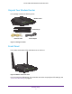
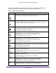
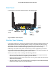
Table Of Contents
- AC1200 WiFi Cable Modem Router
- Contents
- 1. Hardware Setup
- 2. Connect to the Network and Access the Modem Router
- 3. Specify Initial Settings
- 4. Control Access to the Internet
- 5. Share a USB Storage Device Attached to the Modem Router
- USB Device Requirements
- Connect a USB Storage Device to the Modem Router
- Access a USB Drive Connected to the Modem Router From a Windows Computer
- Map a USB Device to a Windows Network Drive
- Access a USB Storage Device That Is Connected to the Modem Router From a Mac
- Control Access to the USB Drive
- Use FTP Within the Network
- View or Change Network Folders on a USB Drive
- Add a Network Folder on a USB Storage Device
- Edit a Network Folder on a USB Storage Device
- Approve USB Storage Devices
- Safely Remove a USB Storage Device
- 6. Specify Network Settings
- View or Change the WAN Settings
- Change the MTU Size
- Set Up a Default DMZ Server
- Change the Modem Router’s Device Name
- Change the LAN TCP/IP Settings
- Specify the IP Addresses That the Modem Router Assigns
- Manage LAN IP Addresses
- Use the WPS Wizard for WiFi Connections
- Specify Basic WiFi Settings
- Change the WiFi Security Option
- Set Up a WiFi Guest Network
- Control the WiFi Radios
- Specify WPS Settings
- Set Up a WiFi Access List
- Dynamic DNS
- Improve Network Connections With Universal Plug-N-Play
- 7. Manage Your Network
- View Modem Router Status
- Reboot the Modem Router
- Change the Router Mode
- View and Manage Logs of Modem Router Activity
- Manage the Modem Router Configuration File
- Change the admin Password
- View Event Logs
- Run the Ping Utility
- Run the Traceroute Utility
- View WiFi Access Points in Your Area
- View or Change the Modem Router WiFi Channel
- Remote Management
- Control the LED Settings
- 8. Specify Internet Port Settings
- 9. Troubleshooting
- A. Supplemental Information

Hardware Setup
8
AC1200 WiFi Cable Modem Router Model C6220
You can use the LEDs to verify status and connections. The following table lists and
describes each LED and button on the front panel of the modem router.
Table 1. LED and button descriptions
LED Description
WPS button with
LED
This button lets you use WPS to join the WiFi network without typing the WiFi password.
The WPS LED blinks during this process and then lights solid.
WiFi On/Off
button with LED
Pressing this button for two seconds turns the WiFi radios in the modem router on and off. If
this LED is lit, the WiFi radios are on. If this LED is off, the WiFi radios are turned off and
you cannot use WiFi to connect to the modem router.
Power
• Green. Power is supplied to the modem router.
• Red. Power is cut of
f due to a thermal error caused by heat. Move the unit to a well
ventilated area and power cycle the unit.
• Off. No power is supplied to the modem router.
Downstream
• Solid green. One or more downstream channels are locked.
• Blinking green.
The unit is scanning for a downstream channel.
• Off. No downstream channel is locked.
Upstream
• Solid green. One or more upstream channels are locked.
• Blinking green.
The unit is scanning for an upstream channel.
• Off. No upstream channel is locked.
Internet
• Solid green. The modem router is online.
• Blinking green.
The modem router is synchronizing with the cable provider’s cable
modem termination system (CMTS).
• Off.
The modem router is offline.
2.4 GHz radio
• Green. The 2.4 GHz radio is on.
• Blinking green.
There is WiFi activity on the 2.4 GHz band.
• Off. The
2.4 GHz radio is off.
5 GHz radio
• Green. The 5 GHz radio is on.
• Blinking green.There is WiFi activity on the 5 GHz band.
• Off. The
5 GHz radio is off.
Ethernet • Green.
A device is connected to an Ethernet port and powered on.
• Blinking green.
The Ethernet port is sending or receiving traffic.
• Off. No device is connected to an Ethernet port.
USB • Green.
A USB device is connected to the port on the back panel.
• Off. No USB device is connected to the port on the back panel.