
User's Manual

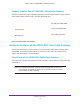
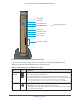
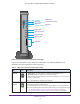
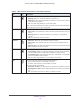

Table Of Contents
- AC1900, N900, and N450 WiFi Cable Data Gateways
- Contents
- 1. Hardware Overview
- 2. Connect and Get Started
- 3. Configure Parental Controls and Basic WiFi Settings
- 4. Manage Internet, WAN, and LAN Settings and Use the WPS Wizard
- 5. Manage the Firewall and Secure Your Network
- 6. Manage and Monitor Your Network
- View the Status and Statistics of the WiFi Cable Data Gateway
- View the WiFi Cable Data Gateway Cable Initialization
- View the Network Map
- View WiFi Channels in Your Environment
- View WiFi Access Points in Your Environment
- View and Manage the Log
- Manage the WiFi Cable Gateway Settings
- Return the WiFi Cable Data Gateway to Its Factory Default Settings
- Reboot the Cable Data Gateway
- 7. Share USB Drives Attached to the Cable Data Gateway
- USB Drive Requirements
- Access a USB Drive on the Network
- Back Up Windows Computers with ReadySHARE Vault
- Specify the Method for Accessing the USB Drive
- View Network Folders on a USB Drive
- Add a Network Folder on a USB Drive
- Change a Network Folder, Including Read and Write Access, on a USB Drive
- Safely Remove a USB Drive
- Enable the Media Server
- 8. Configure Advanced Features
- Manage Advanced WiFi Settings
- Port Forwarding and Port Triggering Concepts
- Set Up Port Forwarding to Local Computers
- Set Up and Manage Port Triggering
- Set Up and Manage IP Address Filtering
- Set Up and Manage MAC Address Filtering
- Configure Dynamic DNS
- Manage the Cable Data Gateway Remotely
- Manage Universal Plug and Play
- Manage the Network Address Translation
- Manage the Ethernet Ports of the LAN Switch
- Manage Network Time Protocol
- 9. Diagnostics and Troubleshooting
- A. Factory Default Settings and Specifications

Hardware Overview
18
AC1900, N900, and N450 WiFi Cable Data Gateways
Power • Solid green. The cable data gateway is receiving power.
• Blinking green. The cable
data gateway is powering on.
• Blinking red. The cable data gateway is performing a self-test or the thermal
cutof
f circuit was triggered.
• Off.
The cable data gateway is not receiving power.
Note: If the Power LED lights red or blinks red at any other time than while booting,
see
Troubleshoot with the LEDs on page 155.
Downstream
• Solid blue. More than one downstream channel is locked.
• Solid green. One downstream channel is locked (channel bonding does not
occur).
• Blinking green.
The cable data gateway is scanning for a downstream
channel.
• Off
. No downstream channel is locked.
Upstream
• Solid blue. More than one upstream channel is locked.
• Solid green. One upstream channel is locked (channel bonding does not
occur).
• Blinking green.
The cable data gateway is scanning for an upstream channel.
• Off
. No upstream channel is locked.
Internet
• Solid green. The cable data gateway is connected to the Internet.
• Slow blinking green. The cable data gateway is receiving DHCP information
from the cable provider
’s cable modem termination system (CMTS).
• Fast blinking green. The
cable
data gateway is downloading a configuration
file from the cable provider’s CMTS.
• Off.
The cable data gateway is not connected to the Internet.
LAN
The type of Ethernet connection determines the LED color:
• A green LED indicates a 1,000 Mbps connection.
• An amber LED indicates a 100/10 Mbps connection.
The LED functions are as follows:
• Solid green or amber. The
Ethernet
port is connected to a powered-on device.
• Blinking green or amber. Data is being transmitted or received on the Ethernet
port.
• Off.
The Ethernet port does not detect a powered-on device.
Table 3. LEDs and front panel buttons of the N450 (continued)
LED Icon Description