
User Manual Part 1


ProSafe Wireless-N VPN Firewall SRXN3205 Reference Manual
Introduction 1-9
v1.0, July 2008
• ProSafe Wireless-N VPN Firewall
• Rubber feet (4) with adhesive backing
• One AC-DC power adpater (12V, 1.5A) with cord (approximately 6 ft, or 183 cm)
• Three dual-band antennas (SMA connectors): 2 dipole (long); 1 patch (square)
• One Straight through Category 5 (Cat5) Ethernet cable.
• Installation Guide, SRXN3205 ProSafe Wireless-N VPN Firewall .
• Resource CD, including:
– Application Notes and other helpful information.
– ProSafe VPN Client Software – one user license.
• Warranty and Support Information Card.
If any of the parts are incorrect, missing, or damaged, contact your NETGEAR dealer. Keep the
carton, including the original packing materials, in case you need to return the firewall for repair.
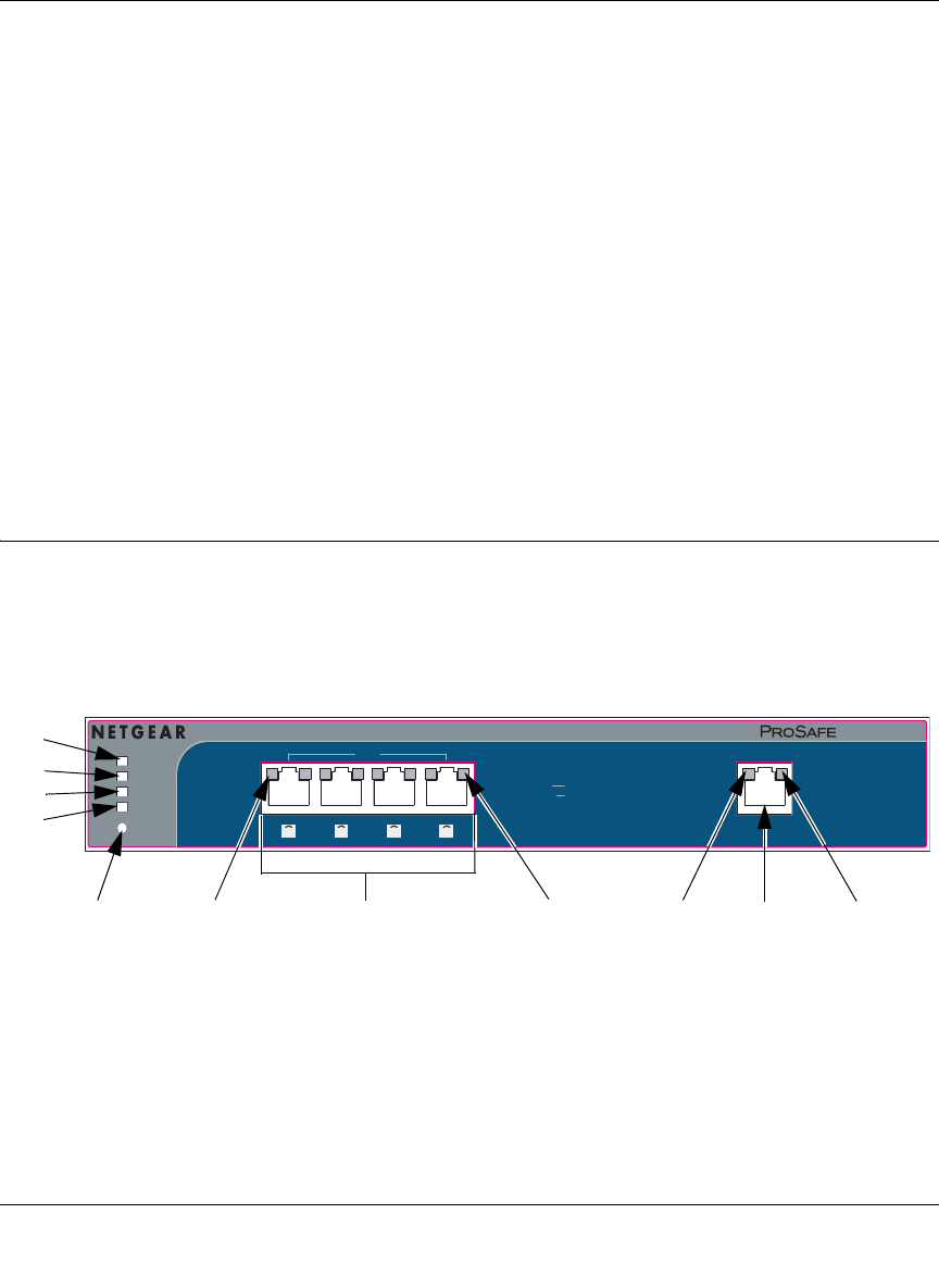
Front Panel Features
The ProSafe Wireless-N VPN Firewall front panel shown below includes two groups of RJ-45
connectors and a column of status indicator light-emitting diodes (LEDs), including Power, Test,
and Band lights:
The column of status indicator light-emitting diodes (LEDs) on the left and the RJ-45 LEDs are
described in Table 1-1., “LED Descriptions”.
Figure 1-1New Photo
41 2 3
Power
Test
n/a 5 GHz
n/g 2.4 GHz
Factory Defaults
SRXN3205
LAN
WAN
Green=1000M
Amber=100MOff=10M
On=Link
Blink=ACT
Left LED
Right LED
1
2
3
4
56 7
89
9
8