
User's Manual

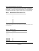
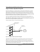


Table Of Contents
- Reference Manual for the NETGEAR ProSafe VPN Client
- Contents
- Chapter 1 About This Manual
- Chapter 2 Introduction
- Chapter 3 Installation
- Chapter 4 Configuring L2TP Connections
- Chapter 5 Using the Security Policy Editor
- What is the Security Policy Editor?
- Basic Steps to Configure a Security Policy
- How to Secure All Connections
- How to Configure Global Policy Settings
- How to Configure Other Connections
- How to Add and Configure a Connection
- How to Enter a Preshared Key
- How to Configure a Gateway
- Configure My Identity
- Configure Security Policy Connection Options
- Configure Authentication (Phase 1)
- Configure Key Exchange (Phase 2)
- Edit a Distinguished Name
- Configure and Manage Connections
- Manage Proposals
- Manage Redundant Gateways
- Manage the Security Policy
- Chapter 6 Using the Certificate Manager
- What is the Certificate Manager?
- Obtain Certificates
- With Online (SCEP) Enrollment
- CAs that Support SCEP
- Retrieve a CA Certificate Online
- Configure a CA Certificate
- Use an HTTP Proxy Server for Online Certificate Requests and CRL Updates
- Import a CA Certificate
- Select a CSP
- Request a Personal Certificate
- Define How Often to Check for and Retrieve New Personal Certificates
- Retrieve a Personal Certificate Manually
- Manage Certificate Requests
- With Manual (File-Based) Enrollment
- Obtain Certificates Through Internet Explorer
- With Online (SCEP) Enrollment
- Manage Certificates
- Manage Certificate Revocation Lists (CRLs)
- Manage the Trust Policy
- Chapter 7 Using Sessions
- Chapter 8 Distributing Customized Profiles
- Chapter 9 Troubleshooting
- Appendix A Networks, Routing, and Firewall Basics
- Appendix B Virtual Private Networking
- Appendix C NETGEAR ProSafe VPN Client to NETGEAR FVS318 or FVM318 VPN Routers
- Appendix D NETGEAR VPN Client to NETGEAR FVL328 or FWAG114 VPN Router
- Glossary
- Index

Reference Manual for the NETGEAR ProSafe VPN Client
Networks, Routing, and Firewall Basics A-5
202-10015-01
Subnet addressing allows us to split one IP network address into smaller multiple physical
networks known as subnetworks. Some of the node numbers are used as a subnet number instead.
A Class B address gives us 16 bits of node numbers translating to 64,000 nodes. Most
organizations do not use 64,000 nodes, so there are free bits that can be reassigned. Subnet
addressing makes use of those bits that are free, as shown below.
Figure A-2: Example of Subnetting a Class B Address
A Class B address can be effectively translated into multiple Class C addresses. For example, the
IP address of 172.16.0.0 is assigned, but node addresses are limited to 255 maximum, allowing
eight extra bits to use as a subnet address. The IP address of 172.16.97.235 would be interpreted as
IP network address 172.16, subnet number 97, and node number 235. In addition to extending
the number of addresses available, subnet addressing provides other benefits. Subnet addressing
allows a network manager to construct an address scheme for the network by using different
subnets for other geographical locations in the network or for other departments in the
organization.
Although the preceding example uses the entire third octet for a subnet address, note that you are
not restricted to octet boundaries in subnetting. To create more network numbers, you need only
shift some bits from the host address to the network address. For instance, to partition a Class C
network number (192.68.135.0) into two, you shift one bit from the host address to the network
address. The new netmask (or subnet mask) is 255.255.255.128. The first subnet has network
number 192.68.135.0 with hosts 192.68.135.1 to 129.68.135.126, and the second subnet has
network number 192.68.135.128 with hosts 192.68.135.129 to 192.68.135.254.
Note: The number 192.68.135.127 is not assigned because it is the broadcast address
of the first subnet. The number 192.68.135.128 is not assigned because it is the network
address of the second subnet.
7262
C
lass B
Network Subnet Node