
User Manual
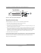
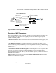


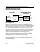
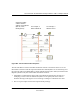
Table Of Contents
- User Manual for the NETGEAR 54 Mbps Wireless USB 2.0 Adapter WG111
- Contents
- Chapter 1 About This Manual
- Chapter 2 Introduction
- Chapter 3 Basic Setup
- Chapter 4 Configuration
- Chapter 4 Troubleshooting
- Basic Tips
- Frequently Asked Questions
- The WG111 status line displays a speed lower than 54 Mbps
- The WG111 Smart Wireless Assistant keeps asking me to save my settings
- Ad Hoc mode is not working correctly
- How to know if the WG111 card has received a valid IP address
- How to use Windows XP’s own Wireless Configuration Utility
- New Hardware Wizard appears after installation has completed
- How to get a PDF copy of the Manual
- Appendix A Technical Specifications
- Appendix B Wireless Networking Basics
- Appendix C Preparing Your PCs for Network Access
- Glossary
- Index

User Manual for the NETGEAR 54 Mbps Wireless USB 2.0 Adapter WG111
B-4 Wireless Networking Basics
202-10026-01
Figure 4-1: 802.11 open system authentication
Shared Key Authentication
The following steps occur when two devices use Shared Key Authentication:
1. The station sends an authentication request to the access point.
2. The access point sends challenge text to the station.
3. The station uses its configured 64-bit or 128-bit default key to encrypt the challenge text, and
sends the encrypted text to the access point.
4. The access point decrypts the encrypted text using its configured WEP Key that corresponds
to the station’s default key. The access point compares the decrypted text with the original
challenge text. If the decrypted text matches the original challenge text, then the access point
and the station share the same WEP Key and the access point authenticates the station.
5. The station connects to the network.
If the decrypted text does not match the original challenge text (i.e., the access point and station do
not share the same WEP Key), then the access point will refuse to authenticate the station and the
station will be unable to communicate with either the 802.11 network or Ethernet network.
This process is illustrated in below.
INTERNET LOCAL
ACT
12345678
LNK
LNK/ACT
100
Cable/DSL
ProSafeWirelessVPN Security Firewall
MODEL
FVM318
PWR TEST
WLAN
Enable
Access Point (AP)
1) Authentication request sent to AP
2) AP authenticates
3) Client connects to network
802.11 Authentication
Open System Steps
Cable or
DLS modem
Client
attempting
to connect