NTC-790/NTC-990 User Manual
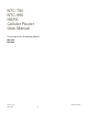
NTC-790 NTC-990 HSPA Cellular Router User Manual This manual covers the following products: NTC-790 NTC-990 Revision 1.
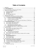
Table of Contents 1 2 Introduction............................................................................................................................4 Cellular Router Overview.......................................................................................................4 2.1 Status Indicators.............................................................................................................5 3 What you will need to configure the Cellular Router ....................................
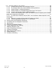
11.2 Common problems and solutions. ................................................................................60 11.2.1 I cannot seem to access the web page interface ..................................................60 11.2.2 The Cellular Router was connected but cannot get back on .................................60 11.2.3 Cellular Router is rebooting frequently ..................................................................60 11.2.4 Cellular Router has connection but cannot access the internet..
1 Introduction Thank you for purchasing the Cellular Router from NetComm. This manual illustrates how to set-up and configure your Cellular Router appropriate for your application. The Cellular Router is configured via a web browser. This manual will take you through the steps required to configure and use your unit correctly. Additionally the router may be configured via the units serial (V.24) port using “AT” (V.
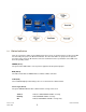
2.1 Status Indicators There are a total of five LED's on the Cellular Router: three green, one amber and one red. The green LED next to the DC power jack is the DC Power Indicator. The other four LED’s are grouped on the opposite end of the router, next to the RF antenna connector. Listed below are the specifications of the LED’s and their corresponding colours. POWER (Green) The green Power LED indicates correct power is applied to the DC power input jack.
RSSI (Green) Of the three radio link status indicators, the green LED is used to show Received Signal Strength. There are three possible states that the RSSI LED can operate in, based upon signal level: Solid : Indicates the RSSI level is -90dbm, or greater (strong) Flashing once per second : Indicates the RSSI level is -110dbm and -90dbm, (medium) Off : Indicates the RSSI level is less than -110dbm (poor) Revision 1.
3 What you will need to configure the Cellular Router You will need the following hardware components to set up the Cellular Router: Power Supply (8-28VDC) Ethernet cable Laptop or PC. Active Telecommunications carrier SIM card (USIM) NOTE – The Ethernet port on the Cellular Router is a DTE non-auto switch so you will need a crossover cable if connected directly to your PC. However, if there is a Hub/Switch connected between the Cellular Router and PC you will need to use a straight through cable.
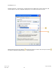
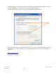
For Windows users: Follow the path Start -> Control Panel -> Network Connections. Right click Local Area Connection and select Properties to open the configuration dialogue box of Local Area Connection as below: Find and click Internet Protocol (TCP/IP) from the protocol list box and then click the Properties button The TCP/IP configuration window will pop up as illustrated below. Revision 1.
Under General tab, select radio button Obtain an IP address automatically and Obtain DNS server address automatically. Then press OK button to close TCP/IP configuration window. Press the Close button to complete the computer preparation for the Cellular Router. Enter the address below in your web browser and connect . The username and password are defined below. Whenever you make changes please refresh your web pages to prevent errors due to caching of web pages. http://192.168.1.
Below illustrates the steps required to access the Cellular Router’s web browser: NOTE – If the Ethernet IP address of the Cellular Router needs to be changed then refer to the section: Configuring the Ethernet IP address. Revision 1.
4 Installing and unlocking the SIM card 4.1 Inserting the SIM card First make sure the SIM card is inserted correctly. You insert the SIM with gold side up and in the direction as shown below: Revision 1.
4.2 Unlocking the SIM If the SIM card is locked you will need to unlock it with a PIN provided with your SIM card. You can find out if the SIM is locked by viewing the SIM Status on the Home page: Revision 1.
If the SIM Status is ENTER PIN as above then do the following: Click on the “Security” Link on the left Revision 1.
When you click on the ‘Security’ link you should see the following message:- Click OK Next, enter the PIN code and confirm the PIN code. Then click Save. Once the SIM has been unlocked you will see a pop up confirming this. Revision 1.
Now Click on the link and the Home Status page should look as below with SIM Status OK: Revision 1.
4.3 Enter PUK If after three attempts you are requested to enter a PUK code: You will need to contact your carrier to obtain this number. Your carrier will issue you a PUK code to enable you to unlock the USIM and enter a new PIN code. Enter the new PIN and PUK codes, press save . If you have entered the PUK correctly you should see the following message: Revision 1.
Now Click on the link and the Home Status page should look as below with SIM Status OK: Revision 1.
4.4 The ‘Remember PIN’ feature This feature is intended to allow the router to automatically send the PIN to the USIM each time the USIM asks for it (usually at power up). The intent of this feature is to ensure that a USIM removed from a router installed in an unattended location by an unauthorized user cannot be used to make calls or otherwise be of any value outside the router on which it is installed.
5 Locking to a specific band You may want to lock the Cellular Router on to a specific band, to do this click on the “Band” link. You may want to do this if you’re using the router in a country with multi frequency networks that may not all support HSPA, you can select the router to only connect on the network frequencies that suit your requirements. Revision 1.
For NTC-790, the following band settings options are applicable. UMTS 850MHz Only = UMTS 850 MHz Only WCDMA ALL = UMTS 850/2100/1900MHz UMTS 850MHz, 2G = UMTS 850 MHz GSM/EDGE/GPRS 900/1800/1900MHz 2G = GSM/EDGE/GPRS 900/1800/1900MHz All Bands (autoband) = UMTS 850/2100/1900MHz GSM/EDGE/GPRS 900/1800/1900MHz For NTC-990, the following 900Mhz band setting options are applicable.
6 How to Establish a Connection to the cellular network This section describes how to set up the Cellular Router to initiate a Wireless connection. There are 2 different ways to set up a wireless connection via PPP:• Initiating the PPP Connection directly from the Cellular Router acting as the PPP Client (most common). • Initiating the PPP Connection from a different PPP client (i.e. laptop or router) with the Cellular Router running in PPPoE mode.
6.1 Initiating a PPP Connection from the Cellular Router The status page of Cellular Router Setup will now be displayed as below. The PPP status on the page should be DISABLED network (as indicated by the large arrow) as your new device is not yet configured to connect to the cellular network. Click the “Data Connection” page. link on the left panel of the screen to open the “Data Connection” web Revision 1.
6.1.1 To connect using a pre-configured profile The cellular router supports 4 connection profiles; these profiles allow you to configure the settings that the router will use to connect to the cellular network. First examine the list of configured profiles Select the profile that you wish to connect to make sure that the APN name field is correct. This is very important. The examples above shows the APN name to be “apnname1/apnname2/apnname3” as examples but yours will be specific to your carrier.
6.1.2 To connect using a user configured profile If none of the pre-configured profiles are suitable you may configure a 4th user defined profile as follows: Select Profile Number 4 Make sure that the APN name field is correct. This is very important. The example above shows the APN name to be “apnname4” as an example but yours will be specific to your carrier. As for the APN, the “User” and “Password” fields carrier.
Once configured you may now connect using this profile as follows: Select the profile that you wish to connect to Click Auto Connect Enable Click Save (4 in this case). . . From now on, Auto Connect will keep remain enabled and the router will automatically connect unless you come back to this page and disable it. Revision 1.
6.1.3 To confirm successful connection Now click on the link to return to the status page. Please pay close attention to PPP field on the page (shown by the arrow). PPP Status should be UP. PPP IP Address shows the current IP address that the network has allocated for the Cellular Router. Your new Cellular Router is now ready to use! Revision 1.
6.1.4 How to establish a Connection using the Cellular Router in PPPoE mode This facility can be found on the LAN page. To enable PPPoE mode: Firstly ensure “Auto Connect” under the “Data Connection” configuration page is disabled. Next open the “LAN” configuration page. Specify the APN you wish to use to suit your carrier . In addition you may specify an optional “Service Name” when a “Service Name” is specified the connected device must use the same service name when connecting.
7 Ethernet Related Commands 7.1 How to configure the Ethernet IP address This facility is available on the LAN page. The default IP of the Ethernet port is 192.168.1.50 with subnet mask 255.255.255.0. If you wish to change this then simply enter the new IP address and click on the ‘Save’ button at the bottom of the page. Since the IP address has changed you will have to re-enter the new IP address configured in your browser to access the configuration pages. 7.
7.3 How to configure the DHCP Server This facility is available on the DHCP page. Use the following procedure to change the Cellular Router DHCP server default settings. Ensure your PC’s Ethernet connector is configured to automatically obtain an IP and DNS server address. When you plug in the Ethernet cable to your PC the Cellular Router should automatically assign it an IP address within 10-15 seconds.
7.3.1 How to configure the DHCP relay agent This facility is available on the DHCP page. To enable DHCP relay simply enable the DHCP relay agent and specify the DHCP server address as below: Enabling DHCP Relay will automatically disable the local DHCP server. Revision 1.
7.3.2 How to configure static DHCP assignments This facility is available on the DHCP page. You may assign a particular IP address to a specific device every that device makes a DHCP request as follows: Click Add Enter a name for the computer or device Enter the computer or device MAC Enter the IP address to assign Click Save Revision 1.
7.4 How to configure your Device’s IP address manually (no DHCP) If your device has a statically set IP address you can have your device to work with the Cellular Router by manually configuring your device to the following settings: Set your devices IP address to any valid IP between 192.168.1.2 and 192.168.1.119 or disable the DHCP server and use any address. Do not use the IP address assigned to the modem’s Ethernet Connector. Subnet to: 255.255.255.0.
8 Advanced Features This section explains other features that you may want to enable depending on your application. Some features can add extra stability and error recovery. Other features are available assist with integrating the router with your application. 8.1 How to configure the Periodic Ping Reset Monitor This facility is available on the “System Monitor” page.
Periodic Ping Disabled An Example Setup: The setup below will ping 10.1.2.3 every 10 minutes, if it fails it then tries to ping 10.1.2.4, if that also fails it then accelerates the ping attempts to once every 60 seconds and if 3 successive ping attempts at the one minute interval fails, the modem will reboot. Periodic Ping Enabled NB: The traffic generated by the periodic ping feature is counted as chargeable usage, please keep this in mind when selecting how often to ping. Revision 1.
8.2 How to configure a Periodic Reset Timer This facility is available on the “System Monitor” page. The router can be configured to automatically reboot on a periodic interval specified in minutes. While this is not necessary, it does ensure that in the case of remote installations it will reboot the router if some anomaly occurs. The default value is 0 which disables the Periodic Reset Timer. The maximum value is 65535 minutes. Revision 1.
8.3 Remote Administration Remote administration can optionally be enabled. You may connect to the IP address of the WAN (cellular) interface on port 8080 once it is connected to the cellular network via a data connection. The IP address below is an example only, yours will be different. http://10.10.10.10:8080 Username admin Password password The port number can be changed via the configuration pages and you can change the password for enhanced security.
8.4 NAT Configuration You can enable or disable NAT simply by clicking on the radio button Configuration page and then clicking the “Save” button Revision 1.
8.4.1 How to configure Port Forwarding This facility is available on the “NAT” configuration page. This is only needed if you need to map inbound requests to a specific port on the Cellular IP address to a device connected on the Ethernet interface, e.g. a web camera. 1 to as many as needed. TCP, UDP, All protocols Specifies either a “Friendly” IP address that is allowed to access the modem or a wildcard IP address of 0.0.0.
Example: Make sure NAT Configuration is enabled by clicking the ‘Enable’ radio button Enter the information as appropriate Click Save NB: If the “Incoming Port Range” specifies a single port (as above) then the destination port can be set to any port. If the “Incoming Port Range” specifies a range of port numbers then the “Destination Port Range” MUST be the same as the “Incoming Port Range”. Revision 1.
Configured mappings are displayed as follows: To delete an entry click on the Delete Entry link Revision 1.55 March 2009 from the list of IP Mappings.
8.5 How to configure dynamic DNS client This facility is available on the “DDNS” configuration page Dynamic DNS provides a method for the cellular router to update and external name server with the routers cellular WAN IP address. To configure dynamic DNS:- Click Enable . Select the Dynamic DNS service that you wish to user Enter your dynamic DNS account credentials Click Save . . Revision 1.55 March 2009 .
8.6 How to configure the Serial PAD (Packet Assembler and Disassembler) The NetComm NTC Cellular Routers include a PAD feature to allow the transport of arbitrary Async serial data over the packet switched (IP) cellular network. Specifically data received on the routers V.24 interface (serial port) can be encapsulated into TCP or UDP packets and sent to a remote host, likewise data contained in TCP or UDP packets received from a remote host may be forwarded to the routers V.24 interface (serial port).
These items may be configured separately for each of the 4 connection profiles. The following items may be configured using the “Modem” page: Baud Rate The serial (V.24) port baud rate. By default the serial line format is 8 data bits, No parity, 1 Stop bit. See “NTCSeriesCellularRouterV250(AT)manual-V1-52” if you need to change the serial line format.
For UDP the 1st bytes of each datagram sent will be set to the contents of the ID field, data follows immediately after the ID; for TCP the ID is transmitted once immediately after the connection is established. Ignore String When the “Ignore String” field is not blank (empty) the router will strip any character sequence that matches the “Ignore String” from the data stream received from the serial port.
• Always Off • PPP On DCD is on when the router has established a PPP session with the cellular network DCD is always off Flow Control • Off Serial port flow control off • Hardware Serial port uses RTS/CTS flow control RI Action Determines how the router controls the state of the serial port RI line • Always On • Incoming Ring RI is on when an incoming connection request is received.
9 Routing Features 9.1 How to configure PPTP Client This page can be accessed by clicking on the PPTP link. There are a couple of steps that you need to take before obtaining a PPTP interface: 1 Get connected on to the Cellular network: To do this click on the 'Data Connection' link and in the PPP Profile Connect section click 'enable' for one of profiles 1-4. To check that the PPP interface is UP click on the Status link and in the PPP section it should indicate UP.
NOTE – It may be necessary to add a static route using the ‘Routing’ link. The PPTP gateway is the PPTP server address and so in the static routes section under the ‘Routing’ link enter the PPTP server IP address in the Gateway IP address box. Example: If the PPTP server address is 203.44.251.100 and the IP address of the local PPTP interface is 10.1.3.42 (i.e a 10.0.0.0 address) then in the static routes section enter the following: • 10.0.0.0 in the destination IP address box • 255.0.0.
9.2 Configuring Static Routes This facility is available on the Routing HTML page. Some routes are added by default by the Cellular Router on initialisation such as the Ethernet subnet route for routing to a device on the Ethernet subnet. A PPP route is also added upon obtaining a Wireless PPP connection. However, if you have other routers (hence networks) on the Ethernet subnet for example, you may want to add some more static routes.
The Active Routing table at the bottom will show the new route added as shown below: Example: If you have a router on the Ethernet side of the Cellular Router with a gateway 192.168.1.5 that interfaces to network 10.123.0.0/16 and you want to get to a device on that network then you enter: 10.123.0.0 in the Destination IP address field 255.255.0.0 in the IP Subnet Mask Field 192.168.1.5 in the Gateway IP address Field The lower the metric value the higher the priority this routes has over other routes.
Deleting Static Routes Select the delete entry text (in blue) for the route as shown above Revision 1.55 March 2009 .
9.3 How to Configure RIP RIP (Routing Information Protocol) is used for advertising routes to other routers. Thus all the routes in the Cellular Router’s routing table will be advertised to other nearby routers. For example, the route for the Cellular Router’s Ethernet subnet could be advertised to a Router on the PPP interface side so that a Router on this network will know how to route to a device on the Cellular Router’s Ethernet subnet.
9.4 How to configure VRRP Virtual Router Redundancy Protocol (VRRP) is a non-proprietary redundancy protocol described designed to increase the availability of the default gateway servicing hosts on the same subnet. This increased reliability is achieved by advertising a "virtual router" (an abstract representation of master and backup routers acting as a group) as a default gateway to the host(s) instead of one physical router.
In the VRRP Configuration section on the Routing HTML page: Click enable Enter the relevant details • enter an id – this is the VRRP id which is different for each virtual router on the network. • enter a priority – a higher value is a higher priority. • enter the VRRP IP address – this is the virtual IP address that both virtual routers share.
10 Router Application and Configuration management Features to manage the cellular routers configuration and application firmware may be found on the Application Load/Saved page: 10.1 To save a copy of the routers configuration Click Save This will download a copy of the current settings from the cellular router to your PC. NB: • It is NOT possible to edit the contents of the file downloaded, if you modify the contents of the configuration file in any way you will not be able to restore it later.
10.2 To restore a copy of the routers configuration Click Browse . Select the configuration file you wish to restore. Click Restore . 10.3 To restore the routers configuration to the factory defaults Click Restore . You will see the following message:- Click OK . The factory default configuration is restored. Revision 1.
10.4 To upgrade to a new router application version Click on the browse button and browse to where the upgrade file is located on your PC/laptop Click Upload You will see the following message:- Click OK . You will see the following message:- Click OK . Revision 1.
The upgrade process will begin. If the upgrade is successful you should see something similar to the following: Revision 1.
11 Troubleshooting 11.1 Viewing the system log To view the routers log file click the “Logfile” link Revision 1.
Revision 1.
11.2 Common problems and solutions. 11.2.1 I cannot seem to access the web page interface The default IP address of the unit is 192.168.1.50, so first try to open a web browser to this address. Also check that your laptop/PC is on the same subnet as the Cellular Router’s Ethernet port. 11.2.2 The Cellular Router was connected but cannot get back on You may need to enable the periodic ping timer using the System Monitor Link on the HTML pages. This ensures that if the connection drops (i.
11.2.5 I cannot seem to get a wireless WAN connection • Click on the Data Connection link on the HTML page and check that the APN is correct. • Also check that the username and password credentials are correct if the APN in use requires these. • Make sure that Auto Connect is enabled on the PPP Profile Connect section on the Data Connection page. 11.2.
11.2.8 How can I reset the cellular router’s IP address to default The IP address can be reset to default by the following actions. Read the following fully as you need to take action at certain points within a short period of time. The reason for forcing these actions is to prevent an accidental overwriting of your non-default IP address. Getting this sequence correct may take a few tries. • Power the unit up with the Ethernet connector NOT PLUGGED IN.
11.2.9 I am having problems getting a PPTP connection. Check the routes on the “Routing” page There should be 5 routes shown. • One route for interface eth0. • Two routes for interface ppp0. • Two routes for interface ppp1. If there are not 5 routes it is most possible:• PPTP is not enabled. • The credentials on the PPTP HTML page are wrong, either the IP address or username, password.
12 RS-232 Serial Port Integration Parameters You can use the guide below to design serial cables to integrate the Cellular Router into your system.
13 RJ-45 Ethernet Port Integration Parameters You can use the guide below to design Ethernet cables to integrate the Cellular Router into your systems.
14 Specifications This section covers the specifications and cable pin outs. Interface Connectors: RS-232 DE-9F Connector (DCE) 10/100 Base-T Full Duplex USB 2.0 Full Speed (12Mbps) Host Controller Power Connector: 2.1mm/5.5mm DC Barrel Jack (Center Positive) LED Indicators: SVC TYPE, Tx/Rx, DCD, RSSI Antenna Interface: 50 ohm SMA Female for Cellular Network (Labeled RF) Size: 140mm L x 80mm W x 44mm H (exclude mounting-brackets) Weight: 250 grams Power Input: 8-28 VDC @ 1.
15 Download and Upload Speeds The speeds here are theoretical maxima; practically they may well be lower. For UMTS HSUPA the upload speed is 1.9Mbps (upgradeable to 5.76Mbps, applicable to model NTC-790 and NTC-990) and 7.2Mbps downstream. NOTE If connected to a LAN via the Ethernet port, the connection status window may display high speeds such as 100Mbps, but this cannot be achieved over-the-air.
17 Additional Software Packs NTC series cellular router covered in this manual supports the following additional software packs. Additional software packs provides the cellular router with add-on functionality and features.
18 Legal & Regulatory Information This manual is copyright. Apart from any fair dealing for the purposes of private study, research, criticism or review, as permitted under the Copyright Act, no part may be reproduced, stored in a retrieval system or transmitted in any form, by any means, be it electronic, mechanical, recording or otherwise, without the prior written permission of NetComm Limited. NetComm Limited accepts no liability or responsibility, for consequences arising from the use of this product.
21 Product Warranty The warranty is granted on the following conditions: 1. This warranty extends to the original purchaser (you) and is not transferable; 2. This warranty shall not apply to software programs, batteries, power supplies, cables or other accessories supplied in or with the product; 3. The customer complies with all of the terms of any relevant agreement with NetComm and any other reasonable requirements of NetComm including producing such evidence of purchase as NetComm may require; 4.
Product Warranty NetComm products have a standard 12 months warranty from date of purchase. However some products have an extended warranty option, via registering your product online at the NetComm website www.netcomm.com.au. Technical Support If you have any technical difficulties with your product, please refer to the support section of our website. www.netcomm.com.