User Guide NB504 YML864 Rev1 ������ NB504 ����� UserRouter ����� Guide 54Mbps Wireless www.netcomm.com.
Contents Package Contents..........................................................................................................................................4 Chapter 1: About this Guide...........................................................................................................................5 1.1 Purposes............................................................................................................................................5 1.2 Conventions..........................
5.7 Forwarding........................................................................................................................................47 5.7.1 Virtual Servers.........................................................................................................................47 5.7.2 Port Triggering.........................................................................................................................49 5.7.3 DMZ............................................................
Package contents The following contents should be found in your box: • One NB504 54Mbps Wireless Router • One AC power Adapter for NB504 54Mbps Wireless Router • Quick Installation Guide • One Resource CD for NB504 54Mbps Wireless Router, including: • This Guide • Other Helpful Information Note: If any of the listed contents are damaged or missing, please contact the retailer from whom you purchased the NB504 54Mbps Wireless Router for assistance. NB504 User Guide YML864Rev1 www.netcomm.com.
Chapter 1: About this Guide Thank you for choosing the NB504 54Mbps Wireless Router. This router provides dedicated solution for Small Office/Home Office (SOHO) networks. With your network all connected, your local wired or wireless network can share Internet access, files and fun for multiple PCs through one ISP account. It is an easy web-based setup for installation and management. Even though you may not be familiar with the router, this guide will make configuring the router easy.
Chapter 2: Introduction 2.1 Overview of the Router The NB504 54Mbps Wireless Router integrates 4-port Switch, firewall, NAT-router and Wireless AP. Its design is dedicated to Small Office/Home Office (SOHO) wireless network solutions. The NB504 54Mbps Wireless Router will allow you to connect your network wirelessly better than ever, sharing Internet Access, files and fun, easily and securely. In the most attentive wireless security, the NB504 54Mbps Wireless Router provides multiple protection measures.
2.2 Features • Complies with IEEE 802.11g, IEEE 802.11b, IEEE 802.3, IEEE 802.3u standards. • 1 10/100M Auto-Negotiation RJ45 WAN port, 4 10/100M Auto-Negotiation RJ45 LAN ports, supporting Auto MDI/MDIX. • Supports 54/48/36/24/18/12/9/6Mbps or 11/5.5/3/2/1Mbps data transfer rates. • Provides WPA/WPA2, WPA-PSK/WPA2-PSK authentication, TKIP/AES encryption security. • Shares data and Internet access for users, supporting PPPoE, Dynamic IP, Static IP, L2TP, PPTP, BigPond Cable Internet access.
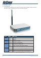
2.3 Panel Layout 2.3.1 The Front Panel The front panel of the NB504 consists of several LED indicators, which is designed to indicate connections. View from left. Table 2-1 describes the LEDs on the front panel of the router.
2.3.2 The Rear Panel The rear panel contains the following features. (View from left to right:) • AC power socket: only use the power adapter supplied with the NB504 54Mbps Wireless Router, use of a different adapter may result in product damage.
Chapter 3: Connecting the Router 3.1 System Requirements • Broadband Internet Access Service (DSL/Cable/Ethernet) • One DSL/Cable modem that has an RJ45 connector • Each PC in the LAN needs a working Ethernet Adapter and an Ethernet cable with RJ45 connectors • TCP/IP protocol must be installed on each PC • Web browser, such as Microsoft Internet Explorer 5.0 or later, Netscape Navigator 6.0 or later 3.
3.3 Connecting the Router Before you install the router, you should connect your PC to the Internet through your broadband service successfully. If there is any problem, please contact your ISP. After that, please install the router according to the following steps. Don’t forget to pull out the power plug and keep your hands dry. 1. Power off your PC, Cable/DSL modem, and the router. 2. Locate an optimum location for the router.
Chapter 4: Quick Installation Guide After connecting the NB504 Router into your network, you should configure it. This chapter describes how to configure the basic functions of your NB504 Wireless Router. These procedures only take you a few minutes. You can access the Internet via the router immediately after successfully configuring. 4.1 TCP/IP configuration The default IP address of the NB504 54Mbps Wireless Router is 192.168.1.1. And the default Subnet Mask is 255.255.255.0.
Open a command prompt, and type ping 192.168.1.1, then press Enter. If the result displayed is similar to that shown in figure 4-1, the connection between your PC and the router has been established. Figure 4-1 Successful result of Ping command If the result displayed is similar to that shown in figure 4-2, it means that your PC has not connected to the router. Figure 4-2 Failed result of Ping command Please check it following these steps: 1.
4.2 Quick Installation Guide With a Web-based (Internet Explorer or Netscape® Navigator) utility, it is easy to configure and manage the NB504 54Mbps Wireless Router. The Web-based utility can be used on any Windows, Macintosh or UNIX OS with a web browser. Connect to the router by typing http://192.168.1.1 in the address field of web browser. Figure 4-3 Login the router After a moment, a login window will appear similar to that shown in Figure 4-4.
If the User Name and Password are correct, you can configure the router using the web browser. Please click the Quick Setup link on the left of the main menu and the Quick Setup screen will appear. Figure 4-5 Quick Setup Click Next, then Choose WAN Connection Type page will appear, shown in figure 4-6. Figure 4-6 Choose WAN Connection Type The router supports three popular ways to connect to Internet. Please select one compatible with your ISP. Click Next to enter the necessary network parameters.
If you Choose “Static IP”, the Static IP settings page will appear, shown in figure 4-8: Figure 4-8 Quick Setup - Static IP Note - The IP parameters should have been provided by your ISP. • IP Address - This is the WAN IP address as seen by external users on the Internet (including your ISP). Enter the IP address into the field. • Subnet Mask - The Subnet Mask is used for the WAN IP address, it is usually 255.255.255.0 • Default Gateway - Enter the gateway IP address into the box if required.
After you complete the above, click Next, the Wireless settings page will appear, shown in figure 4-9. Figure 4-9 Quick Setup - Wireless settings In this page, you can configure the following wireless parameters: • Wireless Radio - Indicates whether the Access Point feature of the router is enabled or disabled. If disabled, the WLAN LED on the front panel will not be lit and the wireless stations will not be able to access the router.
Click the Next button, you will then see the Finish page: Figure 4-10 Quick Setup - Finish After finishing all configurations of basic network parameters, please click Finish button to exit this Quick Setup. NB504 User Guide 18 YML864Rev1 www.netcomm.com.
Chapter 5: Configuring the Router This chapter describes each web page’s key functions. 5.1 login After your successful login, you can configure and manage the router. There are ten main menus on the left of the web-based utility. Submenus will be available after you click one of the main menus. The ten main menus are: Status, Quick Setup, Network, Wireless, DHCP, Forwarding, Security, Static Routing, Dynamic DDNS and System Tools.
5.2 Status The Status page displays the router’s current status and configuration. All information is read-only. 1. LAN This field displays the current settings or information for the LAN, including the MAC address, IP address and Subnet Mask. 2. Wireless This field displays basic information or status for wireless function, including Wireless Radio, SSID, Channel, Mode, Wireless MAC address and IP address. 3.
Figure 5-1 Router Status YML864 Rev1 ������ NB504 ����� User ����� Guide www.netcomm.com.
5.3 Quick Setup Please refer to Section 4.2: “Quick Installation Guide.” 5.4 Network Figure 5-2 the Network menu There are three submenus under the Network menu (shown in figure 5-2): LAN, WAN and MAC Clone. Click any of them, and you will be able to configure the corresponding function. The detailed explanations for each submenu are provided below. 5.4.1 LAN You can configure the IP parameters of LAN on this page.
5.4.2 WAN You can configure the WAN port parameters on this page. First, please choose the WAN Connection Type (Dynamic IP/Static IP/PPPoE/802.1X + Dynamic IP/802.1X + Static IP/BigPond Cable/L2TP/PPTP) for Internet. The default type is Dynamic IP. If you aren’t given any login parameters (fixed IP Address, logging ID, etc), please select Dynamic IP. If you are given a fixed IP (static IP), please select Static IP.
Get IP with Unicast DHCP - A few ISPs’ DHCP servers do not support the broadcast applications. If you cannot get the IP Address normally, you can choose this option. (This is rarely required.) 2. If you choose Static IP, you should have fixed IP Parameters specified by your ISP.
3. If you choose PPPoE, you should enter the following parameters (figure 5-6): Figure 5-6 WAN - PPPoE • • User Name/Password - Enter the User Name and Password provided by your ISP. These fields are case-sensitive. Connect on Demand - You can configure the router to disconnect your Internet connection after a specified period of inactivity (Max Idle Time).
Click the Connect button to connect immediately, Click the Disconnect button to disconnect immediately. Click the Advanced Settings button to set up the advanced option, the page shown in figure 5-7 will then appear: Figure 5-7 PPPoE Advanced Settings • • • • • Packet MTU - The default MTU size is 1492 bytes, which value is usually fine. For some ISPs, you need modify the MTU. This should not be done unless you are sure it is necessary for your ISP.
4. If you choose 802.1X + Dynamic IP, you should enter the follow parameters(figure 5-8) : Figure 5-8 802.1X + Dynamic IP Settings • • • User Name - Enter the user name for 802.1X authentication provided by your ISP Password - Enter the password for 802.1X authentication provided by your ISP. Click Login to start 802.1X authentication. Click Logout to end 802.1X authentication. Host Name - This field is required to be filled by some service provider. YML864 Rev1 ������ NB504 ����� User ����� Guide www.
5. If you choose 802.1X + Static IP, you should enter the follow parameters(figure 5-9) : Figure 5-9 802.1X + Static IP Settings • • • • • User Name - Enter the user name for 802.1X authentication provided by your ISP Password - Enter the password for 802.1X authentication provided by your ISP. Click Login to start 802.1X authentication. Click Logout to end 802.1X authentication. IP Address - Enter the IP address in dotted-decimal notation provided by your ISP.
6. If you choose BigPond Cable, you should enter the following parameters (figure 5-10): Figure 5-10 BigPond Settings • • • • User Name/Password - Enter the User Name and Password provided by your ISP. These fields are case-sensitive. Auth Server - Enter the authenticating server IP address or host name. Auth Domain - Type in the domain suffix server name based on your location. Eg, NSW / ACT - nsw.bigpond.net.au VIC / TAS / WA / SA / NT - vic.bigpond.net.au QLD - qld.bigpond.net.
7. If you choose L2TP, you should enter the following parameters (figure 5-11): Figure 5-11 L2TP Settings • • • User Name/Password - Enter the User Name and Password provided by your ISP. These fields are case-sensitive. Dynamic IP/ Static IP – Choose either as you are given by your ISP. Click the Connect button to connect immediately, Click the Disconnect button to disconnect immediately.
8. If you choose PPTP, you should enter the following parameters (figure 5-12): Figure 5-12 PPTP Settings • • • User Name/Password - Enter the User Name and Password provided by your ISP. These fields are case-sensitive. Dynamic IP/ Static IP – Choose either as you are given by your ISP and enter the ISP’s IP address or the domain name. If you choose static IP and enter the domain name, you should also enter the DNS assigned by your ISP. And click the Save button.
• • Connect Automatically - Connect automatically after the router is disconnected. To use this option, click the radio button. Connect Manually - You can configure the router to make it connect or disconnect manually. After a specified period of inactivity (Max Idle Time), the router will disconnect from your Internet connection, and you will not be able to re-establish your connection automatically as soon as you attempt to access the Internet again. To use this option, click the radio button.
5.4.3 MAC Clone You can configure the MAC address of the WAN port on this page, figure 5-13: Figure 5-13 MAC Address Clone Some ISPs require that you register the MAC Address of your adapter, which is connected to your cable, DSL modem or Ethernet during installation. Changes are rarely needed here. • WAN MAC Address - This field displays the current MAC address of the WAN port, which is used for the WAN port.
5.5 Wireless Figure 5-14 Wireless menu There are three submenus under the Wireless menu (shown in figure 5-14): Wireless Settings, MAC Filtering and Wireless Statistics. Click any of them, and you will be able to configure the corresponding function. The detailed explanations for each submenu are provided below. NB504 User Guide 34 YML864Rev1 www.netcomm.com.
5.5.1 Wireless Settings The basic settings for the wireless network are set on this page, figure 5-15: Figure 5-15 Wireless Settings • SSID - Enter a value of up to 32 characters. The same name (SSID) must be assigned to all wireless devices in your network. The default SSID is Wireless, but it is recommended strongly that you change your networks name (SSID) to a different value. This value is case-sensitive. For example, NETCOMM is NOT the same as Netcomm.
• Channel - This field determines which operating frequency will be used. It is not necessary to change the wireless channel unless you notice interference problems with another nearby access point. • Mode - Select the desired wireless mode. The options are: • 54Mbps (802.11g) - Both 802.11g and 802.11b wireless stations can connect to the router. • 11Mbps (802.11b) - Only 802.11b wireless stations can connect to the router. Note: The default is “54Mbps (802.11g)”, which allows both 802.11g and 802.
Figure 5-15a WPA-PSK/WPA2-PSK • WPA-PSK/WPA2-PSK Passphrase - You can enter a WPA or WPA2 passphrase between 8 and 63 characters long. • Group Key Update Period - Specify the group key update interval in seconds. The value can be either 0 seconds or from 30 seconds and up, 1-29 seconds are not usable figures. Enter 0 to disable the update. Figure 5-15b WPA/WPA2 • Radius Server IP - Enter the IP address of the Radius Server • Radius Port - Enter the port number that the radius service used.
5.5.2 MAC Filtering The Wireless MAC Filtering for wireless networks are set on this page, figure 5-16: Figure 5-16 Wireless MAC address Filtering The Wireless MAC Address Filtering feature allows you to control wireless stations accessing the router, which depend on the station’s MAC addresses. • MAC Address - The wireless station’s MAC address that you want to access. • Status - The status of this entry either Enabled or Disabled. • Privilege - Select the privileges for this entry.
1. Enter the appropriate MAC Address into the MAC Address field. The format of the MAC Address is XXXX-XX-XX-XX-XX (X is any hexadecimal digit). For example: 00-0A-EB-B0-00-0B. 2. Enter a simple description of the wireless station in the Description field. For example: Wireless station A. 3. Privilege - Select the privileges for this entry, one of Allow / Deny / 64-bit / 128-bit / 152-bit. 4.
Note: a) If you select the radio button Allow the stations not specified by any enabled entries in the list to access for Filtering Rules, the wireless station B will still not be able to access the router, however, other wireless stations that are not in the list will be able to access the router.
5.5.3 Wireless Statistics This page shows MAC Address, Current Status, Received Packets and Sent Packets for each connected wireless station.
5.6 DHCP Figure 5-19 The DHCP menu There are three submenus under the DHCP menu (shown in figure 5-19): DHCP Settings, DHCP Clients List and Address Reservation. Click any of them, and you will be able to configure the corresponding function. The detailed explanations for each submenu are provided below. NB504 User Guide 42 YML864Rev1 www.netcomm.com.
5.6.1 DHCP Settings The router is set up by default as a DHCP (Dynamic Host Configuration Protocol) server, which provides the TCP/IP configuration for all the PCs that are connected to the router on the LAN. The DHCP Server can be configured on the page (shown in figure 5-20): Figure 5-20 DHCP Settings • DHCP Server - Enable or Disable the DHCP server. If you disable the Server, you must have another DHCP server within your network or else you must manually configure the computer.
5.6.2 DHCP Clients List This page shows Client Name, MAC Address, Assigned IP and Lease Time for each DHCP Client attached to the router (figure 5-21): Figure 5-21 DHCP Clients List • Index - The index of the DHCP Client • Client Name - The name of the DHCP client • MAC Address - The MAC address of the DHCP client • Assigned IP - The IP address that the router has allocated to the DHCP client. • Lease Time - The time of the DHCP client leased.
5.6.3 Address Reservation When you specify a reserved IP address for a PC on the LAN, that PC will always receive the same IP address each time when it accesses the DHCP server. Reserved IP addresses should be assigned to servers that require permanent IP settings. This page is used for address reservation (shown in figure 5-22). Figure 5-22 Address Reservation • MAC Address - The MAC address of the PC of which you want to reserve IP address.
To Reserve IP addresses: 1. Click the Add New button. (Pop-up figure 5-23) 2. Enter the MAC address (The format for the MAC Address is XX-XX-XX-XX-XX-XX.) and IP address in dotted-decimal notation of the computer you wish to add. 3. Click the Save button when finished. Figure 5-23 Add or Modify a Address Reservation Entry To modify or delete an existing entry: 1. Click the Modify in the entry you want to modify. If you want to delete the entry, click the Delete. 2. Modify the information. 3.
5.7 Forwarding Figure 5-24 The Forwarding menu There are four submenus under the Forwarding menu (shown in figure 5-24): Virtual Servers, Port Triggering, DMZ and UPnP. Click any of them, and you will be able to configure the corresponding function. The detailed explanations for each submenu are provided below. 5.7.1 Virtual Servers Virtual servers can be used for setting up public services on your LAN, such as DNS, Email and FTP.
To setup a virtual server entry: 1. Click the Add New button. (pop-up figure 5-26) 2. Select the service you want to use from the Common Service Port list. If the Common Service Port list does not have the service that you want to use, type the number of the service port or service port range in the Service Port box. 3. Type the IP Address of the computer in the Server IP Address box. 4. Select the protocol used for this application, either TCP or UDP, or All. 5.
5.7.2 Port Triggering Some applications require multiple connections, like Internet games, video conferencing, Internet calling and so on. These applications cannot work with a pure NAT router. Port Triggering is used for some of these applications that can work with an NAT router. You can set up Port Triggering on this page shown in figure 5-27: Figure 5-27 Port Triggering Once configured, operation is as follows: 1.
To add a new rule, enter the following data on the Port Triggering screen. 1. Click the Add New button. (pop-up figure 5-28) 2. Enter a port number used by the application when it generates an outgoing request. 3. Select the protocol used for Trigger Port from the pull-down list, either TCP, UDP, or All. 4. Enter the range of port numbers used by the remote system when it responds to the PC’s request. 5. Select the protocol used for Incoming Ports Range from the pull-down list, either TCP or UDP, or All. 6.
5.7.3 DMZ The DMZ host feature allows one local host to be exposed to the Internet for a special-purpose service such as Internet gaming or videoconferencing. DMZ host forwards all the ports at the same time. Any PC whose port is being forwarded must have its DHCP client function disabled and should have a new static IP Address assigned to it because its IP Address may change when using the DHCP function.
5.7.4 UPnP The Universal Plug and Play (UPnP) feature allows the devices, such as Internet computers, to access the local host resources or devices as needed. UPnP devices can be automatically discovered by the UPnP service application on the LAN. You can configure UPnP on this page that shown in figure 5-30: Figure 5-30 UPnP Settings • Current UPnP Status - UPnP can be enabled or disabled by clicking the Enable or Disable button.
5.8 Security Figure 5-31 The Security menu There are six submenus under the Security menu (shown in figure 5-31): Firewall, IP Address Filtering, Domain Filtering, MAC Filtering, Remote Management and Advanced Security. Click any of them, and you will be able to configure the corresponding function. The detailed explanations for each submenu are provided below. YML864 Rev1 ������ NB504 ����� User ����� Guide www.netcomm.com.
5.8.1 Firewall Using the Firewall page (shown in figure 5-32), you can turn the general firewall switch on or off. The default setting for the switch is off. If the general firewall switch is off, even if IP Address Filtering, DNS Filtering and MAC Filtering are enabled, their settings are ineffective. Figure 5-32 Firewall Settings • Enable Firewall - the general firewall switch is on or off. • Enable IP Address Filtering - set IP Address Filtering is enabled or disabled.
5.8.2 IP Address Filtering The IP address Filtering feature allows you to control Internet Access by specific users on your LAN based on their IP addresses. The IP address filtering are set on this page, figure 5-33: Figure 5-33 IP address Filtering To disable the IP Address Filtering feature, keep the default setting, Disabled. To set up an IP Address Filtering entry, click Enable Firewall and Enable IP Address Filtering on the Firewall page, and click the Add New… button.
7. Pass - Select either Allow or Deny through the router. 8. Status - Select Enabled or Disabled for this entry on the Status pull-down list. 9. Click the Save button to save this entry. To modify or delete an existing entry: 1. Click the Modify in the entry you want to modify. If you want to delete the entry, click the Delete. 2. Modify the information. 3. Click the Save button. Click the Enable All button to make all entries enabled Click the Disabled All button to make all entries disabled.
5.8.3 Domain Filtering The Domain Filtering page (shown in figure 5-35) allows you to control access to certain websites on the Internet by specifying their domains or key words. Figure 5-35 Domain Filtering Before adding a Domain Filtering entry, you must ensure that Enable Firewall and Enable Domain Filtering have been selected on the Firewall page. To Add a Domain filtering entry, click the Add New… button.
To modify or delete an existing entry: 1. Click the Modify in the entry you want to modify. If you want to delete the entry, click the Delete. 2. Modify the information. 3. Click the Save button. Click the Enabled All button to make all entries enabled. Click the Disabled All button to make all entries disabled. Click the Delete All button to delete all entries Click the Next button to go to the next page and the Previous button to return to the previous page.
5.8.4 MAC Filtering Like the IP Address Filtering page, the MAC Address Filtering page (shown in figure 5-37) allows you to control access to the Internet by users on your local network based on their MAC Address. Figure 5-37 MAC address Filtering Before setting up MAC Filtering entries, you must ensure that Enable Firewall and Enable MAC Filtering have been selected on the Firewall page. To Add a MAC Address filtering entry, clicking the Add New… button.
Click the Disabled All button to make all entries disabled. Click the Delete All button to delete all entries Click the Next button to go to the next page and click the Previous button to return to the previous page.
5.8.5 Remote Management You can configure the Remote Management function on this page shown in figure 5-39. This feature allows you to manage your Router from a remote location, via the Internet. Figure 5-39 Remote Management • Web Management Port - Web browser access normally uses the standard HTTP service port 80. This router’s default remote management web port number is 80.
5.8.6 Advanced Security Using Advanced Security page (shown in figure 5-40), you can protect the router from being attacked by TCPSYN Flood, UDP Flood and ICMP-Flood from LAN. Figure 5-40 Advanced Security settings • Packets Statistic interval (5 ~ 60) - The default value is 10. Select a value between 5 and 60 seconds in the pull-down list. The Packets Statistic interval value indicates the time section of the packets statistic.
• Forbid Ping Packet from LAN Port - Enable or Disable forbidding Ping Packet to access the router from the LAN port. The default value is disabled. If enabled, the ping packet from the LAN port cannot access the router. (Defends against some viruses) Click the Save button to save the settings. Click the Blocked DoS Host Table button to display the DoS host table by blocking.
5.9 IP & MAC Binding Setting Figure 5 4- the IP & MAC Binding menu There are two submenus under the IP &MAC Binding menu (shown in Figure 5-42): Binding Setting and ARP List. Click any of them, and you will be able to scan or configure the corresponding function. The detailed explanations for each submenu are provided below. 5.9.1 Binding Setting This page displays the IP & MAC Binding Setting table; you can operate it in accord with your desire. (shown in Figure 5-43).
To add IP & MAC Binding entries: 1. Click the Add New.. button. 2. Enter the MAC Address and IP Address. 3. Select the Bind checkbox. 4. Click the Save button to save it. To modify or delete an existing entry: 1. Find the desired entry in the table. 2. Click Modify or Delete as desired on the Modify column. To find an existing entry: 1. Click the Find button (shown in Figure 5-43). 2. Enter the MAC Address or IP Address. 3. Enter the Find button in the next page (shown in Figure 5-45).
5.9.2 ARP List To manage the computer, you could observe the computers in the LAN by checking the relationship of MAC address and IP address on the ARP list, and you could configure the items on the ARP list also. This page displays the ARP List; it shows all the existing IP & MAC Binding entries (shown in Figure 5-46). Figure 5-46ARP List • MAC Address - The MAC address of the controlled computer in the LAN. • IP Address - The assigned IP address of the controlled computer in the LAN.
5.10 Static Routing A static route is a pre-determined path that network information must travel to reach a specific host or network. To add or delete a route, work in the area under the Static Routing page (shown in figure 5-47). Figure 5-47 Static Routing To add static routing entries: 1. Click the Add New button. (pop-up figure 5-48) 2. Enter the following data: • Destination IP Address - The Destination IP Address is the address of the network or host that you want to assign to a static route.
5.11 Dynamic DDNS The router offers a Dynamic Domain Name System (DDNS) feature. DDNS lets you assign a fixed host and domain name to a dynamic Internet IP Address. It is useful when you are hosting your own website, FTP server, or other server behind the router. Before using this feature, you need to sign up for DDNS service providers such as www.dyndns.org, www.oray.net or www.comexe.cn. The Dynamic DNS client service provider will give you a password or key.
5.11.2 Oray.net DDNS If your selected dynamic DNS Service Provider is www.oray.net, the page will appear as shown in figure 5-50: Figure 5-50 Oray.net DDNS Settings To set up for DDNS, follow these instructions: 1. Type the User Name for your DDNS account. 2. Type the Password for your DDNS account. 3. Click on Enable DDNS. 4. Click the Login button to login the DDNS service. • Connection Status - The status of the DDNS service connection is displayed here.
5.11.3 Comexe.cn DDNS If your selected dynamic DNS Service Provider is www.comexe.cn, the page will appear as shown in figure 5-51: Figure 5-51 Comexe.cn DDNS Settings To set up for DDNS, follow these instructions: 1. Type the domain names your dynamic DNS service provider gave. 2. Type the User Name for your DDNS account. 3. Type the Password for your DDNS account. 4. Click on Enable DDNS. 5. Click the Login button to login to the DDNS service.
5.12 System Tools Figure 5-52 The System Tools menu There are eight submenus under the System Tools menu (shown in figure 5-52): Time, Firmware, Factory Defaults, Backup and Restore, Reboot, Password, Log and Statistics. Click any of them, and you will be able to configure the corresponding function. The detailed explanations for each submenu are provided. YML864 Rev1 ������ NB504 ����� User ����� Guide www.netcomm.com.
5.12.1 Time You can set time manually or get GMT from the Internet for the router on this page (shown in figure 5-53): Figure 5-53 Time settings • Time Zone - Select your local time zone from this pull down list. • Date - Enter your local date in MM/DD/YY into the right blanks. • Time - Enter your local time in HH/MM/SS into the right blanks. Time setting follows these steps below: 1. Select your local time zone. 2. Enter date and time in the right blanks 3. Click Save.
5.12.2 Firmware The page (shown in figure 5-54) allows you to upgrade the latest version firmware to keep your router up-todate. Figure 5-54 Firmware Upgrade New firmware is posted at www.netcomm.com.au and can be downloaded for free. If the router is not experiencing difficulties, there is no need to upgrade firmware, unless the new firmware supports a new feature you need.
5.12.3 Factory Defaults This page (shown in figure 5-55) allows you to restore the factory default settings for the router. Figure 5-55 Restore Factory Default Click the Restore button to reset all configuration settings to their default values. • The default User Name: admin • The default Password: admin • The default IP Address: 192.168.1.1 • The default Subnet Mask: 255.255.255.0 Note: Any settings you have saved will be lost when the default settings are restored. 5.12.
5.12.5 Reboot This page (shown in figure 5-57) allows you to reboot the router. Figure 5-57 Reboot the router Click the Reboot button to reboot the router. Some settings of the router will take effect only after rebooting, which include: • Change LAN IP Address. (System will reboot automatically) • MAC Clone (system will reboot automatically) • DHCP service function. • Static address assignment of DHCP server. • Web Service Port of the router.
5.12.7 Log This page (shown in figure 5-59) allows you to query the logs of the router. Figure 5-59 System Log The router can keep logs of all traffic. You can query the logs to find what happened to the router. Click the Refresh button to refresh the logs. Click the Clear Log button to clear all the logs. NB504 User Guide 76 YML864Rev1 www.netcomm.com.
5.12.8 Statistics The Statistics page (shown in figure 5-60) displays the network traffic of each PC in LAN, including total traffic and traffic of the last Packets Statistic interval seconds. Figure 5-60 Statistics • Current Statistics Status - Enable or Disable. The default value is disabled. To enable, click the Enable button. If disabled, the function of DoS protection in Security settings will be ineffective. • Packets Statistics Interval - The default value is 10.
Appendix A: FAQ 1. How do I configure the router to access Internet by ADSL users? 1) First, configure the ADSL modem configured in RFC1483 bridge model. 2) Connect the Ethernet cable from your ADSL modem to the WAN port on the router. The telephone cord plugs into the Line port of the ADSL modem. 3) Login to the router, click the “Network” menu on the left of your browser, and click “WAN” submenu. On the WAN page, select “PPPoE” for WAN Connection Type.
2. How do I configure the router to access Internet by Ethernet users? 1) Login to the router, click the “Network” menu on the left of your browser, and click “WAN” submenu. On the WAN page, select “Dynamic IP” for “WAN Connection Type”, finish by clicking “Save”. 2) Some ISPs require that you register the MAC Address of your adapter, which is connected to your cable or DSL modem during installation.
3. I want to use Netmeeting, what do I need to do? 1) If you start Netmeeting as a sponsor, you don’t need to do anything with the router. 2) If you start as a responsor, you need configure Virtual Server or DMZ Host. 3) How to configure Virtual Server: Login to the router, click the “Forwarding” menu on the left of your browser, and click “Virtual Servers” submenu.
Figure A-7 Remote Management Note: If the above configuration takes effect, to configure to the router by typing http://192.168.1.1:88 (the router’s LAN IP address: Web Management Port) in the address field of the web browser. 3) Login to the router, click the “Forwarding” menu on the left of your browser, and click the “Virtual Servers” submenu.
5. The wireless stations cannot connect to the router. 1) Make sure the “Wireless Router Radio” is enabled. 2) Make sure that the wireless stations’ SSID accord with the router’s SSID. 3) Make sure the wireless stations have right KEY for encryption when the router is encrypted. 4) If the wireless connection is ready, but you can’t access the router, check the IP Address of your wireless stations. NB504 User Guide 82 YML864Rev1 www.netcomm.com.
Appendix B: Configuring the PC In this section, we’ll introduce how to install and configure the TCP/IP correctly in Windows 95/98. First make sure your Ethernet Adapter is working, refer to the adapter’s manual if needed. 1. Install TCP/IP component (If you use Windows 2000 or later, you can skip this step.) 1) On the Windows taskbar, click the Start button, point to Settings, and then click Control Panel. 2) Double-click the Network icon, click on the Configuration tab in the appearing Network window.
2. Configure TCP/IP for your computer 1) On the Windows taskbar, click the Start button, point to Settings, and then click Control Panel. 2) Double-click the Network icon, highlight the bound TCP/IP tab in the appearing Network window that appears. An example is shown in the following figure: Figure B-3 Configuration tab 3) Click on Properties. The following TCP/IP Properties window will display and the IP Address tab is open on this window by default.
Figure B-5 Gateway tab c. Choose Disable DNS on the DNS configuration tab, as shown in the following figure: Figure B-6 DNS Configuration tab • Setting IP address manually a. Select Specify an IP address on IP Address tab, as shown in the following figure. If the router’s LAN IP address is 192.168.1.1, type IP address is 192.168.1.x (x is from 2 to 254), and subnet mask is 255.255.255.0. YML864 Rev1 www.netcomm.com.
Figure B-7 IP Address tab b. Type the router’s LAN IP address (the default IP is 192.168.1.1) into the New gateway field on the Gateway tab, and click on the Add button, as shown in the figure: Figure B-8 Gateway tab c. On the DNS Configuration tab, click Enable DNS radio, and type your computer name in to the Host field and a Domain (such as szonline.com) into the Domain field.
Figure B-9 DNS Configuration tab • The configuration is now finished and will take effect after rebooting. YML864 Rev1 www.netcomm.com.
Appendix C: Specifications General Standards IEEE 802.3, 802.3u, 802.11b and 802.11g Protocols TCP/IP, PPPoE, DHCP, ICMP, NAT, SNTP Ports One 10/100M Auto-Negotiation WAN RJ45 port, Four 10/100M Auto-Negotiation LAN RJ45 ports supporting Auto MDI/MDIX Cabling Type 10BASE-T: UTP category 3, 4, 5 cable (maximum 100m) EIA/TIA-568 100Ω STP (maximum 100m) 100BASE-TX: UTP category 5, 5e cable (maximum 100m) EIA/TIA-568 100Ω STP (maximum 100m) Radio Data Rate 54/48/36/24/18/12/9/6Mbps or 11/5.
Appendix D: Glossary • 802.11b - The 802.11b standard specifies a wireless networking at 11 Mbps using direct-sequence spread-spectrum (DSSS) technology and operating in the unlicensed radio spectrum at 2.4GHz, and WEP encryption for security. 802.11b networks are also referred to as Wi-Fi networks. • 802.11g - specification for wireless networking at 54 Mbps using direct-sequence spread-spectrum (DSSS) technology, using OFDM modulation and operating in the unlicensed radio spectrum at 2.
Appendix E: Legal & Regulatory Information This manual is copyright. Apart from any fair dealing for the purposes of private study, research, criticism or review, as permitted under the Copyright Act, no part may be reproduced, stored in a retrieval system or transmitted in any form, by any means, be it electronic, mechanical, recording or otherwise, without the prior written permission of NetComm Limited.
Product Warranty The warranty is granted on the following conditions: 1. This warranty extends to the original purchaser (you) and is not transferable; 2. This warranty shall not apply to software programs, batteries, power supplies, cables or other accessories supplied in or with the product; 3. The customer complies with all of the terms of any relevant agreement with NetComm and any other reasonable requirements of NetComm including producing such evidence of purchase as NetComm may require; 4.
Product Warranty NetComm products have a standard 12 months warranty from date of purchase. However some products have an extended warranty option, via registering your product online at the NetComm website www.netcomm.com.au. Refer to the User Guide for complete product warranty conditions, limitations of warranty and other legal and regulatory information. Contact Information If you have any technical difficulties with your product, please do not hesitate to contact NetComm’s Customer Support Department.