Contents 1 Introduction ...............................................................................................................................................4 1.1 Features ..........................................................................................................................................4 1.2 Package Contents ...........................................................................................................................4 1.3 Specification ...........................
10 Utility ....................................................................................................................................................66 10.1 System Info ..................................................................................................................................67 10.2 Config Tool ...................................................................................................................................68 10.3 Upgrade......................................
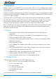
1 Introduction NetComm’s NB712 (2-wire) and NB714 (2 or 4-wire selectable) G.SHDSL 4-port Security Modem Routers deliver symmetrical DSL services to small and medium size business making them an economical alternative to Leased Line or ISDN services. Available in two modem router configurations, the NB712 (2-wire) and NB714 (2 or 4-wire selectable) are capable of providing data rates from 64kbps to 2.304Mbps (NB712) or 128kbps to 4.608Mbps (NB714) and fully comply with the ITU-T G.991.2 standards.
1.3 Specification Routing • Supports IP/TCP/UDP/ARP/ICMP/IGMP protocols • IP routing with static routing and RIPv1/RIPv2 (RFC1058/2453) • IP multicast and IGMP proxy (RFC1112/2236) • Network address translation (NAT/PAT) (RFC1631) • NAT ALGs for ICQ/Netmeeting/MSN/Yahoo Messenger • DNS relay and caching (RFC1034/1035) • DHCP server, client and relay (RFC2131/2132) Bridging • IEEE 802.1D transparent learning bridge • IEEE 802.
ATM QoS • UBR (Unspecified bit rate) • CBR (Constant bit rate) • VBR-rt (Variable bit rate real-time) • VBR-nrt (Variable bit rate non-real-time) AAL5 Encapsulation • VC multiplexing and SNAP/LLC • Ethernet over ATM (RFC 2684/1483) • PPP over ATM (RFC 2364) • Classic IP over ATM (RFC 1577) PPP • PPP over Ethernet for fixed and dynamic IP (RFC 2516) • PPP over ATM for fixed and dynamic IP (RFC 2364) • User authentication with PAP/CHAP/MS-CHAP WAN Interface • SHDSL: ITU-T G.991.
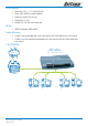
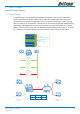
Physical/Electrical • Dimensions: 18.7 x 3.3 x 14.5cm (WxHxD) • Power: 100~240VAC (via power adapter) • Power consumption: 9 watts max • Temperature: 0~45oC • Humidity: 0%~95%RH (non-condensing) Memory • 2MB Flash Memory, 8MB SDRAM Product Information • G.shdsl 2-wire router/bridge with 4-port switching hub LAN, VLAN and business class firewall • G.shdsl 2 or 4-wire selectable router/bridge with 4-port switching hub LAN, VLAN and business class firewall 1.4 Application NB714 or NB712 G.
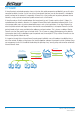
2 Firewall A firewall protects networked computers from an intrusion that could compromise confidentiality or result in data corruption or denial of service. It must have at least two network interfaces, one for the network it is intended to protect, and one for the network it is exposed to. A firewall sits at the junction point or gateway between the two networks, usually a private network and a public network such as the Internet.
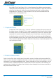
2.1 Types of Firewall There are three types of firewall: 2.1.1 Packet Filtering In packet filtering, only the protocol and the address information of each packet is examined. Its contents and context (its relation to other packets and to the intended application) are ignored. The firewall pays no attention to applications on the host or local network and it “knows” nothing about the source of the incoming data.
2.1.2 Circuit Gateway Also called a “Circuit Level Gateway,” this is a firewall approach that validates connections before allowing data to be exchanged. What this means is that the firewall doesn’t simply allow or disallow packets but also determines whether the connection between both ends is valid according to configurable rules, then opens a session and permits traffic only from the allowed source and possibly only for a limited period of time.
Ping of death On the Internet, ping of death is a kind of denial of service (DoS) attack caused by an attacker deliberately sending an IP packet larger than the 65,536 bytes allowed by the IP protocol. One of the features of TCP/IP is fragmentation; it allows a single IP packet to be broken down into smaller segments. Attackers began to take advantage of that feature when they found that a packet broken down into fragments could add up to more than the allowed 65,536 bytes.
3 VLAN (Virtual Local Area Network) Virtual LAN (VLAN) is defined as a group of devices on one or more LANs that are configured so that they can communicate as if they were attached to the same wire, when in fact they are located on a number of different LAN segments. Because VLAN is based on logical instead of physical connections, it is extremely flexible. The IEEE 802.
as belonging to a particular VLAN based on the value of the VID that is included in the tag header. The presence of the tag header carrying a non-null VID means that some other device, either the originator of the frame or a VLAN-aware bridge, has mapped this frame into a VLAN and has inserted the appropriate VID. The following figure shows the difference between a untagged frame and VLAN tagged frame, where the Tag Protocol Identifier (TPID) is of 0x8100 and it identifies the frame as a tagged frame.
4 Getting to know the router This section will introduce the hardware of the router. 4.1 Front Panel The front panel contains LEDs which show the status of the SHDSL router. Note: The front panel LEDs of the NB712 (2-wire) and NB714 (2 or 4-wire selectable) are identical. The NB714 is shown below.
4.2 Rear Panel The rear panel of the SHDSL router is where all of the cable connections are made. Connectors Description DC-IN Power adaptor inlet: Input voltage 9VDC LAN (1,2,3,4) 10/100BaseT auto-sensing and auto- MDIX for LAN port (RJ-45) CONSOLE RS-232C (DB9) for system configuration and maintenance LINE SHDSL interface for WAN port (RJ-11) RST Reset button to reboot or load factory default The reset button can be used in one of two ways.
5 Connecting your G.SHDSL Modem Router This guide is designed to lead users through the Web Configuration of the G.SHDSL Modem Router in the easiest and quickest way possible. Please follow the instructions carefully. Note: There are three methods to configure the router: serial console, Telnet and Web Browser. Only one configuration application is used to setup the Modem Router at any given time. Select the method you wish to use and continue. For Web configuration, you can skip step 3.
Bridge EoA Route EoA IPoA PPPoA NB712 / NB714 User Guide YML829 Rev1 17
PPPoE Step 5: Install the SHDSL Router Do not turn on the Modem Router until you have completed the Hardware Installation. • Connect the power adapter to the port labelled DC-IN on the rear panel of the product. • Connect the Ethernet cable to the PC. Note: The 4-port modem router supports auto-MDIX switching, so both straight and cross-over Ethernet cables can be used. • Connect the phone cable to the product and the other side of the phone cable to the wall jack.
6 Configuration via Web Browser For Win95, 98 and Me, click the start button. Select Setting and Control Panel. Double click the Network icon. In the Configuration window, select the TCP/IP protocol line associated with your network card and then click the Properties button.
Choose IP Address tab. Select Obtain IP address automatically. Click the OK button. The window will ask you to restart the PC. Click Yes button. After rebooting your PC, open your web browser and type http://192.168.1.1 to connect to the Router. The default IP address and sub net-mask of the Router is 192.168.1.1 and 255.255.255.0. Because the router acts as DHCP server in your network, the router will automatically assign an IP address for the PC in the network.
7 Basic Setup The Basic Setup contains LAN, WAN, Bridge and Router operation modes. This section can be used to completely setup the router. After successfully completing it, you can access the Internet. This is the easiest and quickest way to setup the router. Note: The advanced functions are only for advanced users. The incorrect settings of advanced functions can affect the performance of the network and cause a system error or disconnection. Click Basic for basic installation.
7.1 Bridge Mode Before configuring the router in bridge mode, check with your ISP to ensure you have the necessary information. Click Bridge and CPE Side to setup Bridging mode of the Router and then click Next. Two SHDSL modes are available: CO, Central Office, and CPE, Customer Premises Equipment. For a connection with a DSLAM, the correct SHDSL mode is CPE. For a LAN to LAN connection, one side must be CO and the other side must be CPE.
WAN1 Parameters Enter VPI: Enter VCI: Click LLC Click Next. 0 32 The screen will display the new parameters. Check the parameters and click Restart. The router will reboot with the new settings. Select Continue to configure other parameters.
7.2 Routing Mode Routing mode includes DHCP server, DHCP client, DHCP relay, Point-to-Point Protocol over ATM and Ethernet and IP over ATM and Ethernet over ATM. The type of Internet protocol is provided by your ISP. Click ROUTE and CPE Side then press Next. Two SHDSL modes are available: CO, Central Office, and CPE, Customer Premises Equipment. For connection with a DSLAM, the SHDSL mode is CPE. For a LAN to LAN connection, one side must be CO and the other side must be CPE.
7.2.1 DHCP Client Some ISPs provide a DHCP server service whereby the PC in the LAN can access IP information automatically. To setup the DHCP client mode, follow the procedure. LAN IP Type: Dynamic Click Next to setup WAN1 parameters.
7.2.2 DHCP Server Dynamic Host Configuration Protocol (DHCP) is a communication protocol that allows network administrators to centrally manage and automate the assignment of Internet Protocol (IP) addresses in an organization’s network. Internet Protocol requires that each machine that can connect to the Internet has a unique IP address. When an organization sets up its computer users with a connection to the Internet, an IP address must be assigned to each machine.
Trigger DHCP Service: Server The default setup is Enable DHCP server. If you want to turn off the DHCP service, choose Disable. For example: If the LAN IP address is 192.168.1.1, the IP range of LAN is 192.168.1.2 to 192.168.1.51. The DHCP server assigns the IP form Start IP Address to End IP Address. The legal IP address range is form 0 to 255, but 0 and 255 are reserved for broadcast so the legal IP address range is from 1 to 254.
7.2.3 DHCP relay If you already have a DHCP server on your LAN and you want to use it for DHCP services, the router provides a DHCP relay function. IP Type: Fixed IP Address: 192.168.1.1 Subnet Mask: 255.255.255.0 Host Name: SOHO Some ISPs require the host name as identification. Check with your ISP to see if your Internet service has been configured with a host name. In most cases, this field can be ignored. Trigger DHCP Service: Relay Click Next to setup DHCP server parameters.
7.2.4 PPPoE or PPPoA PPPoA (point-to-point protocol over ATM) and PPPoE (point-topoint protocol over Ethernet) are authentication and connection protocols used by many service providers for broadband Internet access. These are specifications for connecting multiple computer users on an Ethernet local area network to a remote site through common customer premises equipment, which is the telephone company’s term for a modem and similar devices.
Type the ISP1 parameters. Username: test Password: test Password Confirm: test Your ISP will provide the user name and password. Idle Time: 10 If you want your Internet connection to remain on at all times, enter 0 in the Idle Time field. IP Type: There are three IP types, Dynamic, Fixed and IP Unnumbered, which you can setup. The default IP type is Dynamic. It means that ISP PPP server will provide IP information including a dynamic IP address when a SHDSL connection is established. I.e.
Don’t forget to enable LAN: For IP Routing Usage and type IP address on STEP 2 Note: For security, the password will be displayed as asterisk characters. The screen will display the parameters that will be written to EPROM. Check the parameters before writing to EPROM. Press Restart to restart the router with the new parameters or press Continue to setup other parameters.
7.2.5 IPoA or EoA Before configuring the router, check with your ISP to ensure you have the correct parameters. Type the Wan Parameters; VPI: 0 VCI: 33 AAL5 Encap: LLC Protocol: IPoA , EoA , IPoA + NAT or EoA + NAT Click Next to setup the IP parameters. For more information, refer to the section on NAT/DMZ. IP Address: 10.1.2.1 The router’s IP address as seen from the Internet. Your ISP will provide it and you need to specify it here. Subnet mask: 255.255.255.
The screen will display the parameters that will be written to EPROM. Check the parameters before writing to EPROM. Press Restart to restart the router with the new parameters or press Continue to setup other parameters.
8 Advanced Setup Advanced setup contains SHDSL, WAN, Bridge, VLAN, Route, NAT/DMZ, Virtual server and firewall parameters.
8.1 SHDSL You can setup the Annex type, data rate and SNR margin for SHDSL parameters in SHDSL. Click SHDSL. The following screen displays the Advanced SHDSL settings page for the NB712. The NB714 supports an additional 4-wire mode with 4.0608Mbps data rate. The following screen displays the Advanced SHDSL settings page for the NB714 with the option to select the Link Type. Annex Type: There are three Annex types, Annex A (ANSI), Annex B (ETSI), or Annex AB in SHDSL. Check with your ISP.
SHDSL SNR margin: The margin range is from 0 to 10. SNR margin is an index of line connection. You can see the actual SNR margin in STATUS SHDSL. The larger the SNR margin, the better the line connection. If you set the SNR margin in the field to 2, the SHDSL connection will drop and reconnect when the SNR margin is lower than 2. I.e., the device will reduce the line rate and reconnect for better line connection. The screen will display the parameters that will be written to EPROM.
8.2 WAN The SHDSL router supports up to 8 PVCs. WAN 1 was configured via BASIC except QoS. If you want to setup other PVCs, 2 to 8, the parameters are setup in WAN. I.e., you must apply two or more Internet Services with ISPs otherwise you do not need to setup WAN. The WAN Number 1 will be the parameters setup in Basic Setup. If you want to setup another PVC, you can configure them in WAN 2 to WAN 8. Enter the parameters.
If the WAN protocol is IPoA or EoA, leave the ISP parameters as default setting. The system will ignore the information but deleting or leaving blank fields will cause a system error. QoS (Quality of Service): The Traffic Management Specification V4.0 defines ATM service catalogues that describe both the traffic transmitted by users onto a network as well as the Quality of Service that the network needs to provide for that traffic.
8.3 Bridge If your router is setup in bridge mode and you want to setup advanced filter functions, you can use the BRIDGE menu to setup the filter and blocking functions. Click Bridge to setup. Press Add to add the static bridge information. If you want to filter the MAC address of a LAN PC to access the Internet, press Add to establish the filtering table. Enter the MAC address in the MAC address field and select Filter in the LAN field.
The screen will display the parameters that will be written to EPROM. Check the parameters before writing to EPROM. Press Restart to restart the router with the new parameters or press Continue to setup other parameters.
8.4 VLAN Virtual LAN (VLAN) is defined as a group of devices on one or more LANs that are configured so that they can communicate as if they were attached to the same wire, when in fact they are located on a number of different LAN segments. Because VLAN is based on logical instead of physical connections, it is extremely flexible. Click VLAN to configure VLAN. Two types of VLAN are supported: either 802.1Q or Port-Based. Note that only one type of VLAN can be configured at a time. For setting 802.
VID: Virtual LAN ID is a defined ID number from 1 to 4094. PVID: Port VID is an untagged member of a default VLAN. Link Type: Access means the port can receive or send untagged packets. Link Type: Trunk means that the port can receive or send tagged packets. Port-Based VLANs are VLANs where the packet forwarding decision is based on the destination MAC address and its associated port. Click Port-Based VLAN to configure the router and press Reset.
8.5 Route If the Router is connected to more than one network, it may be necessary to set up a static route between them. A static route is a pre-determined pathway that network information must travel to reach a specific host or network. With Dynamic Routing, you can enable the Router to automatically adjust to physical changes in the network’s layout. The Router, using the RIP protocol, determines the network packets’ route based on the least number of hops between the source and the destination.
RIP Version: Authentication required: Poison Reverse: It determines the format and broadcasting method of any RIP transmissions by the gateway. RIP v1: it only sends RIP v1 messages only. RIP v2: it send RIP v2 messages in multicast and broadcast format. None: for RIP, there is no need of authentication code. Password: the RIP is protected by password, authentication code. MD5: The RIP will be decoded by MD5 rather than be protected by password, authentication code.
8.6 NAT/DMZ NAT (Network Address Translation) is the translation of an Internet Protocol address (IP address) used within one network to a different IP address known within another network. One network is designated as the inside network and the other is the outside. Typically, a company maps its local inside network addresses to one or more global outside IP address and changes the global IP addresses of incoming packets back into local IP addresses.
Users of the public network outside the company can access only the DMZ host. The DMZ may typically also have the company’s Web pages so these could serve the outside world. However, the DMZ provides access to no other company data. In the event that an outside user penetrated the DMZ host’s security, the Web pages might be corrupted, but no other company information would be exposed. Press NAT/DMZ to setup the parameters. If you want to enable the NAT/DMZ functions, click Enable.
8.7 Virtual Server Virtual Server allows specific ports on the WAN interface to be re-mapped to services inside the LAN. For example, 69.210.1.8 is assigned to WAN by the ISP and is visible to the Internet but does not actually have any services (other than NAT) running on the gateway. TCP requests made to 69.210.1.8:80 are remapped to the server 1 on 192.168.1.2:80 for working days from Monday to Friday 8 AM to 6PM, other requests with UDP made to 69.210.1.8:25 are remapped to server 2 on 192.168.1.
8.8 Firewall A firewall is a set of related programs that protect the resources of a private network from other networks. It prevents unauthorised users from accessing private data and resources accidentally. Basic Firewall Security This level only enables the NAT firewall and the remote management security. The NAT firewall will take effect if the NAT function is enabled. The default remote management security is to block any WAN side connection to the device.
Automatic Firewall Security Select Automatic Firewall Security. This level enables basic firewall security as well as all DoS protection and the SPI filter function. Press Finish to finish setting up the firewall. The screen will display the parameters, which will be written to EPROM. Check the parameters. Press restart to restart the router or press Continue to setup another function.
Advanced Firewall Security You can determine the security level for special purpose, environment, and applications by configuring DoS protection and defining an extra packet filter with higher priority than the default SPI filter. Note that an improper filter policy may degrade the capability of the firewall and/or even block the normal network traffic. Click Advanced Firewall Security and then press Finish.
Ping of Death: A ping of death attack attempts to crash your system by sending a fragmented packet, when reconstructed is larger than the maximum allowable size. Other known variants of the ping of death include teardrop, bonk and nestea. Land Attack: A land attack is an attempt to slow your network down by sending a packet with identical source and destination addresses originating from your network.
If you want to configure the Packet Filtering Parameters, choose Enable and press Add. Select the protocol and configure the parameters. If you want to ban all of the protocol from the IP (e.g.: 200.1.1.1) to access the all PCs (e.g.: 192.168.1.2 ~ 192.168.1.50) in the LAN, key in the parameter as; Protocol: ANY Direction: INBOUND (INBOUND is from WAN to LAN, and OUTBOUND is LAN to WAN.) Description: Hacker Src. IP Address: 200.1.1.1 Dest. IP Address: 192.168.1.2-192.168.1.50 Press OK to finish.
Filtering Rule for SMTP connection Filtering rule will be configured as follow Index Protocol Direction Action Source Destination Dest. Port Schedule 1 TCP Inbound Permit External Internal 25 Always 2 TCP Outbound Permit Internal External >1023 Always 3 TCP Outbound Permit Internal External 25 Always 4 TCP Inbound Permit External Internal >1023 Always 5 Any Either Deny Any Any Any Always Packet Direction Source Destination Protocol Dest.
Update Filtering Rule Index Protocol Direction Action Source Destination Source Port Dest. Port 1 TCP Inbound Permit External Internal >1023 25 2 TCP Outbound Permit Internal External 25 >1023 3 TCP Outbound Permit Internal External >1023 25 4 TCP Inbound Permit External Internal 25 >1023 5 Any Either Deny Any Any Any Any Action Source Destination Source Port Dest. Port Filtering Result Index Protocol Direction 1 TCP Inbound Permit(A) 192.168.3.
Rule Order The order of the rules affects the filtering result. The filtering process will proceed from top to bottom, changing the order will give a different result. For example: Rule Source Address Destination Address Action A 10.0.0.0 172.16.6.0 Permit B 10.1.99.0 172.16.0.0 Deny C Any Any Deny Where “0” at the last eight bits indicates “from 1 to 254”, “0” at any eight bits preceding “0”, “0.0” or “0.0.0” indicates “from 1 to 254”.
8.9 IP QoS IP QoS allows you to prioritise different types of traffic, thereby ensuring Quality of Service. This is particularly useful for Voice over IP (VoIP) where the amount of bandwidth can affect the line quality in a phone call. Select Enable to enable IP QoS and then click on the Add button to set the IP QoS Policy parameters. Enter the information to define the Policy Rule and click on the OK button.
The screen will display the configured parameters. Check the parameters. In this example 192.168.1.60 is the highest priority; 192.168.1.50 is the second high priority; 192.168.1.40 is the third highest priority and so on.
9 Administration This section details security, simple network management protocol (SNMP) and time synchronous.
9.1 Security For system security, it is suggested that the default user name and password is changed from the default. There are three ways to configure the route: Web browser, telnet and serial console. Press Security to setup the parameters. For greater security, define the Supervisor ID and password for the gateway. If you don’t set them, all users on your network will be able to access the gateway. You can authorize up to five users to access the router via telnet or console.
Trusted Host address pool will setup the IP addresses from which authorized users can configure the gateway. This is the most secure way to setup and control authorised access to the router. Configured 0.0.0.0 will allow all hosts on Internet or LAN to access the router. Leaving blank the Trust Host List will block all PCs from WAN to access the router. I.e. only PCs on the LAN would be able to access the router. If you type the exact IP address in the field, only that host can access the router.
9.2 SNMP Simple Network Management Protocol (SNMP) provides for the exchange of messages between a network management client and a network management agent for remote management of network nodes. These messages contain requests to get and set variables that exist in network nodes in order to obtain statistics, set configuration parameters, and monitor network events. SNMP communications can occur over the LAN or WAN connection.
SNMP status: Enable Access Right: Deny for deny all access Access Right: Read for access read only Access Right: Write for access read and write. Community: Serves as password for access right. Click on the OK button to submit the changes.
SNMP trap is an informational message sent from an SNMP agent to a manager. Click Modify to modify the trap host pool. Version: Select version for trap host (SNMP v1 or SNMP v2). IP: Type the trap host IP Community: Type the community password. The community is setup in community pool. Click on OK to finish the setup. The browser will display the configured parameters. Press Restart to restart the gateway with the new parameters or press Continue to setup other parameters.
9.3 Time Sync Time synchronization is an essential element for any business that relies on an IT system. The reason for this is that these systems all have clocks that are the source of time for files or operations they handle. Without time synchronization, time on these systems can vary and cause firewall packet filtering schedule processes to fail, security to be compromised, and virtual servers to work in wrong schedule. Click on TIME SYNC.
For SNTP, select SNTP v4.0. SNTP service: Enable Time Server: Any time server in the world can be used but it is suggested that you use the nearest timeserver. Time Zone: You have to choose the right time zone. Click on Finish to finish the setup. The browser will display the configured parameters. Press Restart to restart the gateway with the new parameters or press Continue to setup other parameters.
10 Utility This section describes the utility of the router including system information, loading the factory default configuration, upgrading the firmware, logout and restarting the gateway.
10.1 System Info Click on System Info to review the information. The browser will display your system information on the screen.
10.2 Config Tool This configuration tool has three functions: Load Factory Default, Restore Configuration and Backup Configuration. Press Config Tool. Choose the function and then click on Finish. Load Factory Default function: Note: All of the settings will be changed to factory default. On the other hand you will lose all the configured parameters. Restore Configuration: Backup Configuration: 68 Will reload the factory default parameters to the gateway.
10.3 Upgrade You can upgrade the gateway using the upgrade function. Press Upgrade. Browse the file and press OK button to upgrade. The system will reboot automatically after finishing.
10.4 Logout To logout the router, press logout.
10.5 Restart To restart the router, select Restart in UTILITY. Click on the Restart button to reboot the router.
11 Status You can monitor the following: • SHDSL status including mode, Tx power, Bitrate, and Performance information including SNR margin, attenuation and CRC error count. • LAN status will display the MAC address, IP address, Subnet mask and DHCP client table. • WAN status will display the WAN interface information. • Route status will display the routing table of router. • Interface status includes LAN and WAN statistics information.
12 LAN-to-LAN connection with bridge Mode 12.1 CO side Click Bridge and CO Side to setup Bridging mode of the Router and then click Next.
Enter IP: 192.168.1.1 Enter Subnet Mask: 255.255.255.0 Enter Gateway: 192.168.1.1 Enter Host Name: SOHO WAN1 Parameters Enter VPI: 0 Enter VCI: 32 Encap: Click LLC Click Next The screen will display the configured parameters. Check the parameters and click Restart . The router will reboot with the new settings.
12.2 CPE Side Click Bridge and CO Side to setup Bridging mode of the Router and then click Next. LAN Parameters IP Address: Enter192.168.1.2 Subnet Mask: Enter 255.255.255.0 Gateway: Enter 192.168.1.2 Host Name: Enter SOHO WAN1 Parameters VPI: 0 VCI: 32 Encap: LLC Click Next The screen will display the configured parameters. Check the parameters and click Restart . The router will reboot with the new settings.
13 LAN to LAN Connection with Routing Mode 13.1 CO side Click ROUTE and CO Side then press Next. LAN parameters: 76 IP Address: 192.168.20.1 Subnet Mask: 255.255.255.0 Host Name: SOHO DHCP Service: For more DHCP service, review DHCP Service.
WAN Parameters VPI: 0 VCI: 32 AAL5 Encap: LLC Protocol: IPoA , EoA , IPoA + NAT or EoA + NAT Note: The Protocol used in CO and CPE have to be the same. Click Next to setup the IP parameters. Refer to the section NAT/DMZ for more information. IP Address: 192.168.30.1 Subnet mask: 255.255.255.0 Gateway: 192.169.30.2 Click Next The screen will display the parameters that will be written to EPROM. Check the parameters before writing to EPROM.
13.2 CPE side Click ROUTE and CPE Side then press Next. LAN parameters: IP Address: 192.168.10.1 Subnet Mask: 255.255.255.0 Host Name: SOHO DHCP Service: For more DHCP service, review DHCP Service.
VPI: 0 VCI: 32 AAL5 Encap: LLC Protocol: IPoA , EoA , IPoA + NAT or EoA + NAT Note: The Protocol used in CO and CPE have to be the same. Click Next to setup the IP parameters. Refer to the section NAT/DMZ for more information. IP Address: 192.168.30.2 Subnet mask: 255.255.255.0 Gateway: 192.168.30.1 Click Next The screen will display the parameters that will be written to EPROM.
14 Configuration via Serial Console or Telnet with Menu Driven Interface 14.1 Serial Console Check the connectivity of the RS-232 cable from your computer to the serial port of ROUTER. Start your terminal access program with VT100 terminal emulation. Configure the serial link with the following value: Parameter Value Baudrate 9600 Data Bits 8 Parity Check No Stop Bits 1 Flow-control No Press the SPACE key until the login screen appears. When you see the login screen, you can logon to Router.
14.3 Operation Interface For serial console and Telnet management, the Router implements two operational interfaces: command line interface (CLI) and menu driven interface. The CLI mode provides users with a simple command line interface. The menu driven interface is a more user-friendly interface for general operations. The command syntax for CLI is the same as that of the menu driven interface. The only difference is that the menu driven interface displays all available commands for you to select.
14.4 Window structure From top to bottom, the window will be divided into four parts: 1. Product name 2. Menu field: Menu tree is prompted on this field. “>>” symbol indicates the cursor place. 3. Configuring field: You will configure the parameters in this field. < parameters > indicates the parameters you can choose and < more…> indicates that there have submenu in the title. 4. Operation command for help The following table shows the parameters in the brackets.
14.5 Menu Driven Interface Commands Before changing the configuration, familiarize yourself with the operations list in the following table. The Keystroke list are also displayed on the window. Menu Driven Interface Commands Keystroke Description [UP] or I Move to above field in the same level menu. [DOWN] or K Move to below field in the same level menu. [LEFT] or J Move back to previous menu. [RIGHT] or L Move forward to submenu. [ENTER] Move forward to submenu.
14.6 Menu Tree The menu tree is shown below. All configuration commands are included in the Enable directory and are protected by a supervisor password. Unauthorized users can view the status and configuration of the router, but cannot change any configuration information.
14.7 Configuration To setup the router, move the cursor “ >>” to Enable and press the enter key. When the screen appears, type the supervisor password. The default supervisor password is admin. The password will be prompted as a “ * “ symbol for system security. ---------------------------------------------------------------------Command: enable Message: Please input the following information.
Command Description ping Packet internet groper command. admin You can set management features with this command. utility Upgrade software and backup and restore configuration are done via “utility” command.
14.8 Status You can view the status of SHDSL, WAN, route and interface via the status command. Move cursor “ >> “ to status and press enter. >> shdsl wan route interface firewall Show Show Show Show Show SHDSL status WAN interface status routing table interface statistics status firewall status Command Description shdsl The SHDSL status includes line rate, SNR margin, TX power, attenuation and CRC error of the product, and SNR margin, attenuation and CRC error of remote side.
14.9 Show You can view the system information, configuration and configuration via the show command. Move cursor “ >> “ to show and press enter. >> system config script 88 Show general information Show all configuration Show all configuration in command script Command Description system The general information of the system is displayed. config Config command displays detailed configuration information. script Configuration information will display in the command script.
14.10 Write Any changes to the router configuration must be written to EPROM using the write command and the router needs to be rebooted for the changes to take affect. Move cursor to “ >> “ to write and press enter. ---------------------------------------------------------------------Command: write Message: Please input the following information. Are you sure? (y/n): y ---------------------------------------------------------------------- 14.11 Reboot To reboot the router, use reboot command.
14.13.1 User Profile You can use the user command to clear, modify and list the user profiles. You can define up to five users to access the router via console port or telnet in user profile table however users who have the supervisor password can change the configuration of the router. Move the cursor “ >> “ to user and press enter key. >> clear modify list Clear user profile Modify the user profile List the user profile You can delete the user by number using the clear command.
14.13.3 SNMP Simple Network Management Protocol (SNMP) is the protocol not only governing network management, but also the monitoring of network devices and their functions. The router can generate SNMP traps to indicate alarm conditions, and it relies on SNMP community strings to implement SNMP security. This router supports MIB I & II. Move the cursor “ >> “ to snmp and press enter.
14.13.4 Supervisor Password and ID The supervisor password and ID are the last door for security but the most important. Users who access the router via web browser have to use the ID and password to configure the router and users who access the router via telnet or console mode have to use the password to configure the router. Change the ID and password after configuration and save it. When you access to the router again, you have to use the new password.
14.13.5 SNTP Time synchronization is an essential element for any business that relies on an IT system. The reason for this is that these systems all have clocks that are the source of time for files or operations they handle. Without time synchronization, time on these systems can vary and this can cause virtual server schedule processes to fail and system log exposures with wrong data. There are two methods to synchronize time: synchronize with a PC or SNTPv4.
Move the cursor to time_zone and configure where your router is placed. The easiest way to know the time zone offset hour is from your PC clock. Double click the clock at the right corner of monitor and check the time zone. ---------------------------------------------------------------------Command: admin sntp time_zone <-12~12> Message: Please input the following information.
14.14 Utility There are three utility tools, upgrade, backup and restore, embedded in the firmware. You can update the new firmware via TFTP upgrade tools and backup the configuration via TFTP backup tool and restore the configuration via TFTP restore tool. For upgrade, TFTP server with the new firmware will be supported by supplier but for backup and restore, you must have your own TFTP server to backup and restore the file. Move the cursor “ >> “ to utility and press enter.
14.16.2 SHDSL You can setup the SHDSL parameters by the command shdsl. Move the cursor “ >> “ to shdsl and press enter. >> mode Link n*64 type clear margin Configure SHDSL mode Configure SHDSL link Configure SHDSL data rate Configure SHDSL annex type Clear current CRC error count Configure SHDSL SNR margin There are two types of SHDSL mode, STU-R and STU-C. STU-R means the terminal of central office and STU-C customer premises equipment. Link type will be 2-wire or 4-wire mode according to the product.
14.16.3 WAN The router supports up to 8 PVCs, private virtual circuits, and so you can setup up to 8 WANs; WAN1 to WAN8. Move the cursor “ >> “ to wan and press enter. To setup WAN1, type 1. ---------------------------------------------------------------------Command: setup wan <1~8> Message: Please input the following information.
14.16.4 Bridge You can setup the bridge parameters in bridge command. If the product is configured as a router, you do not want to setup the bridge parameters. Move the cursor “ >> “ to bridge and press enter. >> gateway static Default gateway Static bridging table You can setup default gateway IP via gateway command. You can define 20 sets of static bridge in static command.
14.16.5 VLAN Virtual LAN (VLAN) is defined as a group of devices on one or more LANs that are configured so that they can communicate as if they were attached to the same wire, when in fact they are located on a number of different LAN segments. Because VLAN is based on logical instead of physical connections, it is extremely flexible. You can setup the Virtual LAN (VLAN) parameters in vlan command. The router support the implementation of VLAN-to-PVC only for bridge mode operation, i.e.
14.16.6 802.11Q VLAN Follow the following steps to configure 802.11q VLAN. ---------------------------------------------------------------------Command: setup vlan active Message: Please input the following information. Tigger VLAN function (Tab select) : 8021Q ---------------------------------------------------------------------- To modify the VLAN rule, move the cursor “ >> “ to modify and press enter.
14.16.7 Route You can setup the routing parameters in route command. If the product is configured as a bridge, you do not want to setup the route parameters. Move the cursor “ >> “ to route and press enter. >> static rip Configure static routing table Configure RIP tool If the Router is connected to more than one network, it may be necessary to set up a static route between them. A static route is a pre-determined pathway that network information must travel to reach a specific host or network.
14.16.8 LAN LAN interface parameters can be configured LAN IP address, subnet mask and NAT network type. >> address attrib LAN IP address and subnet mask NAT network type 14.16.9 IP share You can configure Network Address Translation (NAT), Port Address Translation (PAT) and Demilitarized Zone parameters in ip_share menu. Move the cursor “>>” to ip_share then press enter.
14.16.10 NAT You can configure NAT parameters in nat menu. >> virtual global fixed Virtual IP address pool Global IP address pool Fixed IP address mapping The virtual menu contains range of virtual IP address, delete virtual IP address and show virtual IP address. >> range delete list Edit virtual IP address pool Delete virtual IP address pool Show virtual IP address pool You can create up to five virtual IP address pool ranges in range command.
To modify fixed IP address mapping, move the cursor “>>” to fixed command and press enter. >> modify Modify fixed NAT mapping interface Bind address pair to specific interface delete Delete fixed NAT mapping list Show fixed IP address mapping You can create up to 10 fixed NAT mapping entries via range command. ---------------------------------------------------------------------Command: setup ip_share nat fixed modify <1~1o> Message: Please input the following information.
14.16.11 PAT To configure Port Address Translation, move the cursor “>>” to pat and press enter. >> clear modify list Clear virtual server mapping Modify virtual server mapping Show virtual server mapping pool You can delete virtual server mapping entry- from 1 to 10- by using clear command. You can create up to 10 virtual server mapping entry via modify command.
14.16.12 DMZ To setup demilitarized zone, move the cursor “>>” to dmz and press enter. >> active address Trigger DMZ host function Configure virtual IP address and interface You can enable the demilitarized zone via active command. After enabling the DMZ, shift the cursor to address and press enter. ---------------------------------------------------------------------Command: setup ip_share dmz address <1~10> Message: Please input the following information. Virtual IP address: 192.168.1.
14.16.14 Packet Filtering Packet filtering function can be configured by pkt_filter command. Move the cursor to pkt_filter and press enter. >> active drop_flag add delete modify exchange list Trigger packet filtering function Drop fragment packets Add packet filtering rule Delete packet filtering rule Modify packet filtering rule Exchange the filtering rule Show packet filtering table To enable the packet filtering function, you can use active command. Add the packet filtering rule via add command.
14.16.15 DoS Protection DoS protection parameters can be configured in dos_protection menu. Move the cursor to dos_protection and press enter.
14.16.16 IPQoS IP QoS is a function to decide the priorities of setting IPs to transfer packets under the situation of overloading bandwidth. To configure IP QoS function, move the cursor to IPQoS and press enter. >> Active Add Delete Modify list Trigger IP QoS function Add IP QoS policy Delete IP QoS policy Modify IP QoS policy Show IP QoS policy table You can enable the IPQoS function via active command.
14.16.17 DHCP Dynamic Host Configuration Protocol (DHCP) is a communication protocol that lets network administrators to manage centrally and automate the assignment of Internet Protocol (IP) addresses in an organization’s network. Using the Internet Protocol, each machine that can connect to the Internet needs a unique IP address. When an organization sets up its computer users with a connection to the Internet, an IP address must be assigned to each machine.
14.16.18 DNS proxy You can setup three DNS servers in the router. The number 2 and 3 DNS servers are optional. Move cursor “ >> “ to dns_proxy and press enter. ---------------------------------------------------------------------Command: setup dns_proxy [IP] [IP] Message: Please input the following information. DNS server 1 (ENTER for default) <168.95.1.1>: 10.0.10.1 DNS server 2: 10.10.10.1 DNS server 3: ---------------------------------------------------------------------- 14.16.
Appendix A: Cable Information This cable information is provided for your reference only. Please ensure you only connect the appropriate cable into the correct socket on either this product or your computer. If you are unsure about which cable to use or which socket to connect it to, please refer to the hardware installation section in this manual. If you are still not sure about cable connections, please contact a professional computer technician or NetComm for further advice.
Straight and crossover cable configuration There are two types of the wiring: Straight-Through Cables and Crossover Cables. Category 5 UTP/STP cable has eight wires inside the sheath. The wires form four pairs. Straight-Through Cables has same pinouts at both ends while Crossover Cables has a different pin arrangement at each end. In a straight-through cable, wires 1,2,3,4,5,6,7 and 8 at one end of the cable are still wires 1~8 at the other end.
SHDSL Line Connector Console Cable 114 Pin Number Description 1 No connection 2 RxD (O) 3 TxD (I) 4 No connection 5 GND 6 No connection 7 CTS (O) 8 RTS (I) 9 No connection NB712 / NB714 User Guide YML829 Rev1
Appendix B: Registration and Warranty Information All NetComm Limited (“NetComm”) products have a standard 12 month warranty from date of purchase against defects in manufacturing and that the products will operate in accordance with the specifications outlined in the User Guide. However some products have an extended warranty option (please refer to your packaging).
Product Warranty The warranty is granted on the following conditions: 1. This warranty extends to the original purchaser (you) and is not transferable; 2. This warranty shall not apply to software programs, batteries, power supplies, cables or other accessories supplied in or with the product; 3. The customer complies with all of the terms of any relevant agreement with NetComm and any other reasonable requirements of NetComm including producing such evidence of purchase as NetComm may require; 4.