Contents Introduction .................................................................................................................... 3 Gigabit Ethernet Technology ............................................................................ 4 Switching Technology ...................................................................................... 4 Features ........................................................................................................................ 5 Package Contents .....
Introduction Congratulations on your purchase of the NetComm 5-Port 1000BASE-T Gigabit Ethernet Switch. The following guide will take you through the installation and application of your Switch as well as provide information about Gigabit Ethernet and switching technology. Rev.1 - YML671 NP3005 - 5 Port Gigabit Switch www.netcomm.com.
Gigabit Ethernet Technology Gigabit Ethernet is an extension of IEEE 802.3 Ethernet utilizing the same packet structure, format, and support for CSMA/CD protocol, full duplex, flow control, and management objects, but with a tenfold increase in theoretical throughput over 100-Mbps Fast Ethernet and a hundredfold increase over 10-Mbps Ethernet.
Features The NetComm 5-Port 1000BASE-T Gigabit Ethernet Switch has been designed for easy installation and high performance in an environment where traffic on the network and the number of users increase continuously.
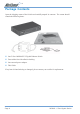
Package Contents Open the shipping carton of the Switch and carefully unpack its contents. The carton should contain the following items: ■ One 5-Port 1000BASE-T Gigabit Ethernet Switch ■ Four rubber feet with adhesive backing ■ One external power adapter ■ This Guide If any item is found missing or damaged, please contact your reseller for replacement. www.netcomm.com.au Page 6 Rev.
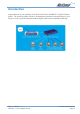
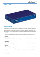
Front Panel The figure below shows the front panels of the switch. Front panel view of the Switch LED Indicators Comprehensive LED indicators display the conditions of the Switch and status of the network. The LED indicators of the Switch include Power, Link/Act, 1000Mbps and 100Mbps. The following shows the LED indicators for the Switch along with an explanation of each indicator. ■ POWER This indicator lights up green when the Switch is receiving power. Otherwise, it is off.
Rear Panel The rear panel of the Switch consists of an DC power connector. The following figure shows the rear panel of the Switch. 5 - RJ45 10/100/1000 Mbps Ports Power Rear panel view of the Switch DC Power Jack: Power is supplied through an external AC power adapter. Check the technical specification section for information about the AC power input voltage. 1000BASE-T Ports: Five Gigabit Ethernet ports of 10/100/1000Mbps AutoNegotiation interface. www.netcomm.com.au Page 8 Rev.
RJ-45 Network ports All of the ports on the NP3005 are 10/100/1000 Mbps capable auto-sensing Ethernet ports. Each port supports only unshielded twisted pair (UTP) cable using an 8-pin RJ-45 plug. The Auto-uplink feature senses the connection of uplink (MDI-II) wiring using a straight-through twisted pair cable to any of the 5 ports on the NP3005 switch to allow for connection to any port of an addition switch or hub.
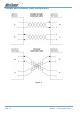
Straight and crossover cable configuration Figure 5 www.netcomm.com.au Page 10 Rev.
Application examples The NP3005 switch is designed to provide full flexibility in configuring your network connections. The switch can be used as a standalone device or it can be used in an up linked mode to other 10/100/1000 Mbps hubs, switches or other interconnection devices - such as internet gateways and routers. Figure 6 below illustrates the NP3005 in a basic network environment connected to several Desktop computers sharing files and peripherals.
Cascading the switch When attaching the NP3005 switch to a router or other devices, be sure to verify the port type implemented before connecting any cable. Figure 7 Connecting using Category 5/5e twisted–pair cables with RJ-45 plugs: Your NP3005 switch supports an Auto-Detect UP-Link port feature on each of the 5 x RJ-45 ports available on this switch. Connect one end of a straight-through cable to the NP3005 switch. Connect the other end of the cable to any port of another NP3005 switch.
Preparation before connecting your switch Before you install your switch, make sure you will be operating the unit within the specified voltage and temperature limits. To install your switch on a flat surface, simply adhere the included rubber feet within the outlines on the bottom surface of the unit. Ensure the switch is positioned with at least 50mm of space on all sides for adequate ventilation.
Attaching computers to the switch 1. Install a 10/100/1000 Mbps (10/100Base-TX) network adapter card into every computer you want to attach to the network. Make sure you install the Network adaptor drivers in accordance with the manufacturers directions. 2. Prepare the twisted-pair cables with RJ-45 plugs on each end. Use Category 5/5e cable for all connections. Make sure the cable length is less than or equal to no more than 100 metres (328 feet). 3.
NB3005 Specifications General Standards: IEEE 802.3ab 1000BASE-T IEEE 802.3u 100BASE-TX IEEE802.3 10BASE-T IEEE 802.3x Flow Control Protocol: Data Transfer Rate: CSMA/CD Ethernet: Fast Ethernet: Gigabit Ethernet: 10Mbps (Half-duplex) 20Mbps (Full-duplex) 100Mbps (Half-duplex) 200Mbps (Full-duplex) 2000Mbps (Full-duplex) Topology: Network Cables: Star Ethernet: 2-pair UTP Cat. 3,4,5, Unshield Twisted Pair (UTP) Cable Fast Ethernet: 2-pair UTP Cat.
Registering your NetComm Product To ensure that the conditions of your warranty are complied with, please go to the NetComm web site for quick and easy registration of your product at www.netcomm.com.au Alternatively, you can fill in the Warranty Registration Form and mail it to NetComm Limited, PO Box 1200, Lane Cove NSW 2066. Contact Information If you have any technical difficulties with your product, please do not hesitate to contact NetComm’s Customer Support Department. Email: support@netcomm.com.
Cut along the line Warranty Registration Form Date of Purchase ……….......………………...........………................................. Name ……….......………………...........………................................. Company ……….......………………...........………................................. Address ……….......………………...........………................................. …………………….........………...........Post Code ......…………...………. Tel No ( ) ..............………....……. Fax No ( E-mail ) ..............……….........……. ..............
Product Warranty The warranty is granted on the following conditions: 1. This warranty extends to the original purchaser (you) and is not transferable; 2. This warranty shall not apply to software programs, batteries, power supplies, cables or other accessories supplied in or with the product; 3. The customer complies with all of the terms of any relevant agreement with NetComm and any other reasonable requirements of NetComm including producing such evidence of purchase as NetComm may require; 4.