
User's Manual
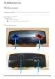


Table Of Contents

POE-02 Installation Guide
3
v1.0
ITEM
DESCRIPTION
1
Blue RJ45 port
Provides Data + Power to the antenna.
2
Red RJ45 port
Provides Power to the Residential Gateway.
3
Power switch
Turns the antenna power supply on or off.
4
IEC-C8 (Figure 8) power inlet
Accepts the included power cable to provide power to the Antenna Power Supply.
POE-02 LED indicators
The table below describes the status of the POWER and ANTENNA LEDs on the PoE injector.
LED
STATUS
DESCRIPTION
POWER
Solid green
PoE injector is connected to AC power.
ANTENNA
Solid green
PoE injector is connected to AC power and the POE port is connected to the OWA.
POWER
ANTENNA