
User's Manual


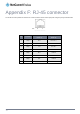


Appendix F: RJ-45 connector
The RJ-45 connector provides an interface for a data connection and for device input power using the pin layout shown below.
Pin: 8 1
Figure 98 -The RJ-45 connector
PIN COLOUR
SIGNAL (802.3AF
MODE A)
SIGNAL (802.3AF
MODE B)
1
White/Orange
stripe
Rx + Rx + DC +
2 Orange Solid Rx - Rx - DC +
3
White/Green
stripe
Tx + Tx + DC -
4 Blue solid DC + unused
5
White/Blue
stripe
DC + unused
6 Green solid Tx - Tx - DC -
7
White/Brown
stripe
DC - unused
8 Brown solid DC - unused
Table 28 - RJ-45 connector pin outs
102
NetComm Wireless CDMA M2M Router
www.netcommwireless.com