CDMA M2M Router NWL-11 USER GUIDE
Copyright Copyright© 2013 NetComm Wireless Limited. All rights reserved. The information contained herein is proprietary to NetComm Wireless. No part of this document may be translated, transcribed, reproduced, in any form, or by any means without prior written consent of NetComm Wireless. Note: This document is subject to change without notice.
Table of contents Table of contents .................................................................................................................................3 Overview ...........................................................................................................................................4 Introduction.......................................................................................................................................................................................
Overview Introduction This document provides you all the information you need to set up, configure and use the NetComm Wireless NWL-11 CDMA M2M Router. Target audience This document is intended for system integrators or experienced hardware installers who understand telecommunications terminology and concepts. Prerequisites Before continuing with the installation of your CDMA M2M Router, please confirm that have the following: A device with a working Ethernet network adapter.
Product introduction Product overview Dual-band CDMA (BC0/BC1), 800/1900MHz CDMA data speeds up to 3.1 Mbps DL Ethernet port with full passive Power over Ethernet (PoE) support (802.
Product features The NetComm Wireless NWL-11 CDMA M2M Router is an M2M device designed by NetComm Wireless to address the rapid growth in M2M deployments. It has been designed to provide state-of-the-art features and versatility at an affordable price. Compatible with North American CDMA networks, the NWL-11 can be managed remotely even when the router does not have an Internet connection via the use of SMS commands and diagnostics.
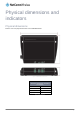
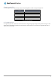
Physical dimensions and indicators Physical dimensions Below is a list of the physical dimensions of the CDMA M2M Router. Figure 1 – CDMA M2M Router Dimensions CDMA M2M ROUTER (WITHOUT EXTERNAL ANTENNA ATTACHED) Length 140 mm Depth 103 mm Height 30 mm Weight 180g Table 2 - Device Dimensions www.netcommwireless.
LED indicators The CDMA M2M Router uses 7 LEDs to display the current system and connection status.
Signal strength LEDs The following table lists the signal strength range corresponding with the number of lit signal strength LEDs. NUMBER OF LIT LEDS SIGNAL STRENGTH All LEDs unlit < -109 dBm 1 -109 dBm to -101dBm 2 -101 dBm to -91 dBm 3 -91 dBm to -85 dBm 4 -85 dBm to -77 dBm 5 > -77 dBm Table 4 - Signal strength LED descriptions LED update interval The signal strength LEDs update within a few seconds with a rolling average signal strength reading.
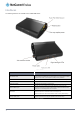
Interfaces The following interfaces are available on the CDMA M2M Router: Figure 3 - Interfaces ITEM DESCRIPTION Main antenna socket SMA female connector for an optional external antenna (not supplied). The main internal antenna is disabled when an external antenna is connected but the auxiliary antenna remains active to provide (where possible) diversity assistance. Power LED Indicates the power status of the device and whether the device is in recovery mode.
Placement of the router When selecting a location to mount the CDMA M2M router, keep in mind that it houses two high performance internal antennas designed to provide optimum signal strength in a wide range of environments. If you find the signal strength is weak, try moving the router to a different place or mounting it differently. If signal strength doesn’t improve, you may need to attach an external antenna (not included) to the router’s female SMA connector.
Perpendicular to the wall If a large surface area is not available, there is the option of mounting the router perpendicular to the wall. This gives the router a small wall footprint while remaining securely attached. Use appropriately sized screws in the mounting holes provided on the back of the unit. Figure 5 - Wall mount - Perpendicular to the wall C Section DIN Rail mount The CDMA M2M router easily slides onto a C Section DIN rail so that it is horizontally mounted.
Mounting bracket The provided mounting bracket provides additional methods of mounting the CDMA M2M router. To attach the mounting bracket, slide it onto the rear of the router as shown in the diagram below: Figure 8 - Sliding on the mounting bracket To remove the bracket, press the PUSH button and slide the router off the bracket: Figure 9 - Removing the mounting bracket www.netcommwireless.
Using the mounting bracket for wall mounting By first attaching the DIN rail bracket to the wall, the CDMA M2M router can be easily attached and removed from the bracket.
Desk mount In situations where wall mounts and DIN rails are not required, you can simply place the CDMA M2M router on a desk using its rubber feet to prevent it from slipping. Figure 13 - Desk mount www.netcommwireless.
Powering the router The CDMA M2M router can be powered in one of three ways: 1. Power over Ethernet (802.3af PoE) 2. DC power input via 2-pin connector (8-35V DC) 3. DC power input via field terminated power source (8-35V DC) The green power LED on the router lights up when a power source is connected. Power over Ethernet (802.3af PoE) Power over Ethernet (PoE) is a method of connecting network devices through Ethernet cable where power and data are passed along a single cable.
Failover power support The CDMA M2M router includes support for connection of two power sources at the same time. When a PoE Ethernet cable is connected and DC power is also supplied to the DC input jack of the router, the router will source power exclusively from the PoE source. In the event that power from the PoE cable is lost, the router will automatically switch to source power from the DC input jack, without affecting the router’s operation.
Installation and activation of the CDMA M2M router Installing the router After you have mounted the router and connected a power source, follow these steps to complete the installation process. 1. Connect equipment that requires network access to the Ethernet port of your router. This may be your computer for advanced configuration purposes, or your end equipment which requires data access via the CDMA M2M router. You can connect one device directly, or several devices using a network switch.
Activating the router The CDMA M2M Router requires activation on the network before it can be used. The router is not activated until you perform the activation process. To perform the activation process: 1. Log in to the router as described above. The Status page is displayed and the router prompts you to activate it by displaying the following pop-up window: 2. Click the OK button on the pop-up window. The router displays “Programming In Progress”.
Advanced configuration The CDMA M2M Router comes with preconfigured settings that should suit most customers. For advanced configuration, log in to the web-based user interface of the router as described in the previous section. The following sections detail the advanced configuration options available on the CDMA M2M Router. Status The status page of the web interface provides system related information and is displayed when you log in to the CDMA M2M router management console.
ITEM DEFINITION System information System up time The current uptime of the router. Board version The hardware version of the router. Router Serial Number The serial number of the router. Software The software version number running on the router. Model The type of phone module and the firmware version of the module. Firmware The firmware revision of the phone module. MDN The Mobile Directory Number of the router on the network. LAN IP The IP address and subnet mask of the router.
Internet The Internet section provides configuration options for Wireless WAN, LAN, Routing and VPN connectivity. Data connection The data connection page allows you to configure and enable/disable the connection profile. Figure 19 – Data connection settings NetComm Wireless CDMA M2M Router 22 www.netcommwireless.
ITEM DEFINITION WWAN (3G) Profile Settings Activation Status Shows whether the router has been activated on the network. MEID The mobile equipment identifier (MEID) of the router, a unique code for identifying devices on a CDMA network. Profile Toggles the WWAN connection on and off. Phone number User The CDMA username provided for the router by your carrier. Password The CDMA password provided for the router by your carrier.
Connecting to the mobile broadband network NetComm Wireless CDMA M2M Router 24 www.netcommwireless.
Manually configuring a connection profile To manually configure a connection profile: 1. Click the Profile toggle key to turn the profile ON. Additional settings appear. Figure 21 - Data connection settings - Profile turned on 2. In the Phone number field, enter the phone number assigned to the device. 3. In the User and Password fields, enter the username and passwords assigned to your account by the carrier. 4.
9. Use the NAT Masquerading toggle key to turn NAT Masquerading on or off. NAT masquerading, also known simply as NAT is a common routing feature which allows multiple LAN devices to appear as a single WAN IP via network address translation. In this mode, the router modifies network traffic sent and received to inform remote computers on the internet that packets originating from a machine behind the router actually originated from the WAN IP address of the router’s internal NAT IP address.
Dial on Demand The dial on demand feature keeps the Packet Data Protocol (PDP) context deactivated by default while making it appear to locally connected devices that the router has a permanent connection to the mobile broadband network. When a packet of interest arrives or an SMS wake-up command is received, the router attempts to establish a mobile broadband data connection. When the data connection is established, the router monitors traffic and terminates the link when it is idle.
Excluding certain packet types from triggering the connection to dial Depending on your environment, you might prefer to exclude certain types of traffic passing through the router from triggering the data connection. You can tell the router to ignore outbound TCP, UDP or ICMP packets. When any of these options are checked the router will not dial a connection when that type of outbound destined data packet reaches the router from a locally connected device.
OPTION DESCRIPTION Keep online for this period of time after a triggered dial When traffic as per the configured settings above appear, the router will either continue to stay online, or dial a connection and will not disconnect it for the specified time period (min. 1 minute, max. 1 hour). This timer is continuously reset throughout the duration of a dial-up session, whenever data activity is detected matching the rules above.
Band Settings The band settings page lets you configure the roaming preference and mode of the radio. LAN LAN configuration The LAN configuration page is used to configure the LAN settings of the router and to enable or disable DNS Masquerading. Figure 31 – LAN configuration settings The default IP of the Ethernet port is 192.168.1.1 with subnet mask 255.255.255.0. To change the IP address or Subnet mask, enter the new IP Address and/or Subnet mask and click the Save button.
With DNS masquerading OFF, the DHCP server hands out the upstream DNS server IP addresses to downstream clients directly, so that downstream clients send DNS requests directly to the upstream DNS servers without being proxied by the CDMA M2M router. You may also override the DNS Masquerading option by specifying custom DNS Server IP addresses in the DHCP Server configuration mentioned in the next section of this guide.
Automatic IP address assignment (DHCP) The DHCP page is used to adjust the settings used by the router’s built in DHPC Server which assigns IP addresses to locally connected devices. DHCP relay configuration In advanced networks configurations where the CDMA M2M router should not be responsible for DHCP assignment, but instead an existing DHCP server is located on the Wireless WAN connection, the clients behind the CDMA M2M router are able to communicate with the DHCP server when DHCP relay is enabled.
OPTION DESCRIPTION DHCP Start Range Sets the first IP address of the DHCP range DHCP End Range Sets the last IP address of the DHCP range DHCP Lease Time (seconds) The length of time in seconds that DHCP allocated IP addresses are valid Default Domain Name Suffix Specifies the default domain name suffix for the DHCP clients. A domain name suffix enables users to access a local server, for example, server1, without typing the full domain name server1.domain.
Dynamic DHCP client list The Dynamic DHCP client list displays a list of the DHCP clients. If you want to reserve the current IP address for future use, click the Clone button and the details will be copied to the address reservation list fields. Remember to click the Save button under the Address reservation list section to confirm the configuration. Figure 35 - Dynamic DHCP client list NetComm Wireless CDMA M2M Router 34 www.netcommwireless.
Routing Static Static routing is the alternative to dynamic routing used in more complex network scenarios and is used to facilitate communication between devices on different networks. Static routing involves configuring the routers in your network with all the information necessary to allow the packets to be forwarded to the correct destination. If you change the IP address of one of the devices in the static route, the route will be broken.
Figure 37 - Adding a static route Active routing list Static routes are displayed in the Active routing list. Figure 38 - Active routing list Deleting static routes From the static routing list, click the icon to the right of the entry you wish to delete. Figure 39 - Deleting a static route NetComm Wireless CDMA M2M Router 36 www.netcommwireless.
RIP RIP (Routing Information Protocol) is used for advertising routes to other routers. Thus all the routes in the router’s routing table will be advertised to other nearby routers. For example, the route for the router’s Ethernet subnet could be advertised to a router on the PPP interface side so that a router on this network will know how to route to a device on the router’s Ethernet subnet. Static routes must be added manually according to your requirements. See Adding Static Routes.
Redundancy (VRRP) Virtual Router Redundancy Protocol (VRRP) is a non-proprietary redundancy protocol designed to increase the availability of the default gateway servicing hosts on the same subnet. This increased reliability is achieved by advertising a “virtual router” (an abstract representation of master and backup routers acting as a group) as a default gateway to the host(s) instead of one physical router.
NAT The Port forwarding list is used to configure the Network Address Translation (NAT) rules currently in effect on the router. Figure 42 – Port forwarding list The purpose of the port forwarding feature is to allow mapping of inbound requests to a specific port on the WAN IP address to a device connected on the Ethernet interface. Adding a port forwarding rule To create a new port forwarding rule: 1. Click the +Add button. The port forwarding settings screen is displayed. 2.
DMZ The Demilitarized Zone (DMZ) allows you to configure all incoming traffic on all protocols to be forwarded to a selected device behind the router. This feature can be used to avoid complex port forwarding rules, but it exposes the device to untrusted networks as there is no filtering of what traffic is allowed and what is denied. The DMZ configuration page is used to specify the IP Address of the device to use as the DMZ host. Figure 44 - DMZ configuration 1.
Figure 46 - Current MAC / IP/ Port filtering rules in effect 5. Enter the details of the rule in the section that is displayed and click the Save button. Figure 47 - MAC / IP / Port filtering settings www.netcommwireless.
OPTION DESCRIPTION Bound Use the drop down list to select the direction of the traffic for which you want to apply to the rule. Inbound refers to all traffic that is entering the router including data entering from the WAN and the LAN. Outbound refers to all traffic exiting the router including traffic leaving in the direction of the WAN and traffic leaving in the direction of the LAN. Forward specifies traffic that enters on the LAN or WAN side and is forwarded to the opposite end.
VPN A Virtual Private Network (VPN) is a tunnel providing a private link between two networks or devices over a public network. Data to be sent via a VPN needs to be encapsulated and as such is generally not visible to the public network. The advantages of a VPN connection include: Data Protection Access Control Data Origin Authentication Data Integrity Each VPN connection has different configuration requirements.
Figure 50 – IPSec profile edit NetComm Wireless CDMA M2M Router 44 www.netcommwireless.
The following table describes each of the fields of the IPSec VPN Connection Settings page. ITEM DEFINITION IPSec Profile Enables or disables the VPN profile. Profile Name A name used to identify the VPN connection profile. Remote IPSec Server Address The IP address of the IPSec server. Remote LAN Address Enter the IP address of the remote network for use on the VPN connection. Remote LAN Subnet Mask Enter the subnet mask in use on the remote network.
OpenVPN OpenVPN is an open source virtual private network (VPN) program for creating point-to-point or server-to-multi-client encrypted tunnels between host computers. It can traverse network address translation (NAT) and firewalls and allows authentication by certificate, pre-shared key or username and password. OpenVPN works well through proxy servers and can run over TCP and UDP transports.
Certificate Authentication In the Certificate Management section, enter the required details to create a client certificate. All fields are required. When you have finished entering the details, click the Generate button. Figure 52 - OpenVPN server configuration – Certificate management When it is done, you can click the Download button to save the certificate file.
Figure 53 – OpenVPN server profile settings NetComm Wireless CDMA M2M Router 48 www.netcommwireless.
Username / Password Authentication In the Username/Password section, enter the username and password you would like to use for authentication on the OpenVPN Server. Click the Download CA certificate button to save the ca.crt file. This file will need to be provided to the client. Note: If you wish to have more than one client connect to this OpenVPN server, you must use Certificate authentication mode as Username/Password only allows for a single client connection.
Certificate Authentication In the Certificate upload section at the bottom of the screen, click the Browse button and locate the certificate file you downloaded when you configured the OpenVPN server. When it has been selected, click the Upload button to send it to the router. Figure 55 - OpenVPN client - Certificate upload Username / Password Authentication Enter the username and password to authenticate with the OpenVPN server.
Figure 57 - OpenVPN P2P mode settings 4. Use the Server port field to select a port number and then use the drop down list to select a packet type to use for the OpenVPN server. The default OpenVPN port is 1194 and default packet type is UDP. 5. In the Local IP Address and Remote IP Address fields, enter the respective local and remote IP addresses to use for the OpenVPN tunnel. The slave should have the reverse settings of the master. 6.
PPTP Client The Point-to-Point Tunnelling Protocol (PPTP) is a method for implementing virtual private networks using a TCP and GRE tunnel to encapsulate PPP packets. PPTP operates on Layer 2 of the OSI model and is included on Windows computers. Configuring the PPTP Client To configure the PPTP client: 1. From the menu bar at the top of the screen, click Networking and then from the VPN section on the left side of the screen, click PPTP client. The PPTP client list is displayed.
7. From the Authentication type drop down list, select the Authentication type used on the server. If you do not know the authentication method used, select any and the router will attempt to determine the correct authentication type for you. There are 5 authentication types you can choose from: CHAP – uses a three way handshake to authenticate the identity of a client.
GRE tunnelling The Generic Route Encapsulation (GRE) protocol is used in addition to Point-to-Point Tunnelling Protocol (PPTP) to create VPNs (virtual private networks) between clients and servers or between clients only. Once a PPTP control session establishes the VPN tunnel GRE is used to securely encapsulate the data or payload. Configuring GRE tunnelling To configure GRE tunnelling: 1.
7. In the Remote tunnel address field, enter the IP address you want to assign to the remote tunnel. 8. In the Remote network address field, enter the IP address scheme of the remote network. 9. In the Remote network/mask field, enter the subnet mask of the remote network. 10. The TTL (Time To Live) field is an 8-bit field used to remove an undeliverable data packet from a network to avoid unnecessary network traffic across the internet.
Services Dynamic DNS The DDNS page is used to configure the Dynamic DNS feature of the router. A number of Dynamic DNS hosts are available from which to select. Figure 62 – Dynamic DNS settings Dynamic DNS provides a method for the router to update an external name server with the current WAN IP address. To configure dynamic DNS: 1. Click the DDNS configuration toggle key to switch it to the ON position. 2. From the Dynamic DNS drop down list, select the Dynamic DNS service that you wish to use.
Network time (NTP) The NTP (Network Time Protocol) settings page allows you to configure the CDMA M2M router to synchronize its internal clock with a global Internet Time server and specify the time zone for the location of the router. This provides an accurate timekeeping function for features such as System Log entries and Firewall settings where the current system time is displayed and recorded. Any NTP server available publicly on the internet may be used. The default NTP server is 0.netcomm.pool.ntp.
Watchdogs Watchdogs are features which monitor the router for anomalies and restart the router if an anomaly occurs preventing its normal operation. When configured, the watchdogs feature transmits controlled ping packets to 1 or 2 user specified IP addresses to confirm an active connection. If the watchdog does not receive responses to the pings after a specified number of failures, it will reboot the device in a last resort attempt to restore connectivity.
Configuring Periodic PING settings The Periodic PING settings configure the router to transmit controlled ping packets to 2 specified IP addresses. If the router does not receive responses to the pings, the router will reboot. To configure the ping watchdog: 1. In the First destination address field, enter a website address or IP address to which the router should send the first round of ping requests. 2.
SNMP SNMP configuration The SNMP page is used to configure the SNMP features of the router. Figure 65 - SNMP configuration SNMP (Simple Network Management Protocol) is used to remotely monitor the router for conditions that may warrant administrative attention. It can be used to retrieve information from the router such as the signal strength, the system time, the interface status, etc. To configure SNMP: 1. Click the SNMP toggle key to switch it to the ON position. 2.
SNMP traps SNMP traps are messages from the router to the Network Management System sent as UDP packets. They are often used to notify the management system of any significant events such as whether the link is up or down. Configuring SNMP traps To configure SNMP traps: 1. In the Trap destination field, enter the IP address to which SNMP data is to be sent. 2. In the Heartbeat interval field, enter the number of seconds between SNMP heartbeats. 3.
TR-069 The TR-069 (Technical Report 069) protocol is a technical specification also known as CPE WAN Management Protocol (CWMP). It is a framework for remote management and auto-configuration of end-user devices such as customer-premises equipment (CPE) and Auto Configuration Servers (ACS). It is particularly efficient in applying configuration updates across networks to multiple CPEs.
HTTPS What is HTTP Secure? HTTP Secure or HTTPS is the use of the HTTP protocol over an SSL/TLS protocol. It is used primarily to protect against eavesdropping of communication between a web browser and the web site to which it is connected. This is especially important when you wish to have a secure connection over a public network such as the internet. HTTPS connections are secured through the use of certificates issued by trusted certificate authorities such as VeriSign.
CODE COUNTRY CODE COUNTRY CODE COUNTRY CODE COUNTRY AX Åland Islands ER Eritrea LS Lesotho SA Saudi Arabia AD Andorra ES Spain LT Lithuania SB Solomon Islands AE United Arab Emirates ET Ethiopia LU Luxembourg SC Seychelles AF Afghanistan FI Finland LV Latvia SE Sweden AG Antigua and Barbuda FJ Fiji LY Libya SG Singapore AI Anguilla FK Falkland Islands (Malvinas) MA Morocco SH St.
3. When you have entered all the required details, press the Generate button. The certificate takes several minutes to generate. When the certificate has been generated, you are informed that it has been successfully generated and installed. The web server on the router restarts and you are logged out of the router. Click OK to be taken back to the login screen. Figure 69 - New certificate successfully generated message www.netcommwireless.
SSH Server Configuration Secure Shell (SSH) is UNIX-based command interface and network protocol used to gain secure access to a remote computer, execute commands on a remote machine or to transfer files between machines. It was designed as a replacement for Telnet and other insecure remote shell protocols which send information, including passwords, as plain text. SSH uses RSA public key cryptography for both connection and authentication.
SMS Diagnostics and Commands SMS messaging The CDMA M2M router offers an advanced SMS feature set, including sending messages, receiving messages, redirecting incoming messages to another destination, as well as supporting remote commands and diagnostics messages. Some of the functions supported include: Ability to send a text message via a CDMA network and store it in permanent storage. Ability to receive a text message via a CDMA network and store it in permanent storage.
OPTION DEFINITION General SMS configuration SMS messaging Toggles the SMS functionality of the router on and off. Messages per page (10-50) The number of SMS messages to display per page. Must be a value between 10 and 50. Encoding scheme The encoding method used for outbound SMS messages. GSM 7-bit mode permits up to 160 characters per message but drops to 50 characters if the message includes special characters.
SMS forwarding configuration Incoming text messages can be redirected to another mobile device and/or a TCP/UDP message server. Redirect to mobile You can forward incoming text messages to a different destination number. This destination number can be another mobile phone or a 3G router phone number. For Example: If someone sends a text message and Redirect to mobile is set to “+61412345678”, the text message is stored on the router and forwarded to “+61412345678” at the same time.
New message The New message page can be used to send SMS text messages to a single or multiple recipients. A new SMS message can be sent to a maximum of 100 recipients at the same time. After sending the message, the result is displayed next to the destination number as “Success” or “Failure” if the message failed to send. By default, only one destination number field is displayed.
Inbox / Outbox The Inbox displays all received messages that are stored on the router while the Outbox displays all sent messages. Figure 73 - SMS Inbox Figure 74 - SMS Outbox ICON DESCRIPTION Forward button. Click this button to open a new message window where you can forward the corresponding message to another recipient. Reply button. Click this button to open a new message window where you can reply to the sender. Add to White list.
Diagnostics The Diagnostics page is used to configure the SMS diagnostics and command execution configuration. This enables you to change the configuration, perform functions remotely and check on the status of the router via SMS commands. SMS diagnostics and command execution configuration Figure 75 - SMS diagnostics and command execution configuration The options on this page are described below. Enable remote diagnostics and command execution Enables or disables the remote diagnostics feature.
Send Set command acknowledgment replies The CDMA M2M router will automatically reply to certain types of commands received, such as get commands, or execute commands. However replies from the CDMA M2M router are optional with set commands and the Wakeup command. This option Enables or disables sending an acknowledgment message after execution of a set command or SMS Wakeup command. If disabled, the router does not send any acknowledgement after execution of a set command or SMS Wakeup command.
White list for diagnostic or execution SMS The white list is a list of mobile numbers that you can create which are considered “friendly” to the router. If Only accept authenticated SMS messages is enabled in the diagnostics section, the router will compare the mobile number of all incoming diagnostic and command messages against this white list to determine whether the diagnostic or command should be executed. You may optionally configure a password for each number to give an additional level of security.
Sending an SMS diagnostic command Follow the steps below to configure the router to optionally accept SMS diagnostic commands only from authenticated senders and learn how to send SMS diagnostic commands to the router. 1. Navigate to the Services > SMS messaging > Diagnostics page 2. Confirm that the Enable remote diagnostics and command execution toggle key is set to the ON position. If it is set to OFF click the toggle key to switch it to the ON position. 3.
SMS Command format Generic Format for reading variables: get VARIABLE PASSWORD get VARIABLE Generic Format for writing to variables: set VARIABLE=VALUE PASSWORD set VARIABLE=VALUE Generic Format for executing a command: Execute COMMAND PASSWORD execute COMMAND Replies Upon receipt of a successfully formatted, authenticated (if required) command, the gateway will reply to the SMS in the following format: TYPE SMS CONTENTS get command “VARIABLE=VALUE” set command “Successfully set VARIABLE to VALUE” ex
A password (if required), only needs to be specified once per SMS, but can be prefixed to each command if desired. “PASSWORD get Variable1”; “get VARIABLE2” “PASSWORD set VARIABLE1=VALUE1”; “set VARIABLE2=VALUE2” If the command sent includes the “reboot” command and has already passed the white list password check, the device keeps this password and executes the remaining command line after the reboot with this same password.
The following table lists valid variables where “x” is a profile number (1-6). If no profile is specified, variables are read from or written to for the current active profile. If a profile is specified, variables are read from or written to for the specified profile number (‘x’). # RDB VARIABLE NAME SMS VARIABLE NAME READ/ WRITE DESCRIPTION Read: link.profile.x.enable (profile no,apn,user,pass,auth,iplocal,status) link.profile.x.apn 0 link.profile.x.user profile link.profile.x.pass or link.
NETWORK TYPE DESCRIPTION 7 Indicates a 3G network 1 Indicates a 2G network Table 20 - Network types returned by get plmnscan SMS command OPERATOR STATUS DESCRIPTION 1 Indicates an available operator which may be selected. 2 Indicates a forbidden operator which may not be selected (applies only to generic SIM cards). 4 Indicates the currently selected operator.
Notes about the set forceplmn command: If the manual selection fails, the device will fall back to the previous ‘good’ network. When enabled, the SMS acknowledgement reply reflects the success or failure of the manual selection with respect to the set command and includes the final MNC/MCC that was configured. Confirming the currently configured operator and network type You can retrieve the currently configured operator and network type using the get forceplmn command.
default settings Required PASSWORD execute factorydefaults Send SMS to retrieve status of router Not required get status Required PASSWORD get status Send SMS to retrieve the history of the session, including start time, end time and total data usage Not required get sessionhistory Required PASSWORD get sessionhistory Send SMS to configure the router to send syslog to a remote syslog server Not required set syslogserver Required PASSWORD set syslogserver Not required A zero byte class 1 f
System Log The Log pages are used to display or download the System log and IPSec logs on the router. System log The System Log enables you to troubleshoot any issues you may be experiencing with your CDMA M2M router. Log data is stored in RAM and therefore, when the unit loses power or is rebooted it will lose any log information stored in RAM. To ensure that log information is accessible between reboots of the router there are two options: 1. Enable the Log to non-volatile memory option 2.
Figure 77 - System log ITEM DEFINITION All Display all system log messages. Debug Show extended system log messages with full debugging level details. Info Show informational messages only. Notice Show normal system logging information. Warning Show warning messages only. Error Show error condition messages only. Table 23 - System log detail levels www.netcommwireless.
IPSec log The IPSec log section provides the ability for you to download the log for the IPSec VPN function. This can assist in troubleshooting any problems you may have with the IPSec VPN. Use the Log level drop down list to specify the type of detail you want to capture in the log and then click the Save button. When you change the logging level, any active IPSec VPN tunnels will be disconnected as a change in logging level requires the IPSec service to be restarted.
System configuration Settings backup and restore The settings backup and restore page is used to backup or restore the router’s configuration or to reset it to factory defaults. In order to view the settings page you must be logged into the web user interface as root using the password admin.
Upload The Upload page allows you to upload firmware files, HTTPS certificates or user created application packages to the CDMA M2M router. When firmware files have been uploaded, they can also be installed from this page. PDF files, such as this user guide may also be uploaded for access on the router’s help page. For more information on application development, contact NetComm Wireless about our Software Development Kit.
igure 81 - File upload F The recovery firmware image is listed in the Uploaded files section. Click the Install link to begin installing the recovery firmware image and then click OK on the confirmation window that appears. Figure 82 - Uploaded files 3. The recovery firmware image is flashed and when it is complete, the router displays “The firmware update was successful” and returns to the main Upload screen. Figure 83 - Recovery firmware flash process 4.
Figure 84 – NWL Series Router Recovery Console banner 6. Click the Application installer link from the menu bar at the top then click the Browse button. Locate the main firmware image file on your computer and click Open. Click the Upload button to begin the firmware upload. Figure 85 - Recovery console - Upload main firmware image 7. When the upload has completed, the screen refreshes to display the list of files on the router’s storage.
Software applications manager The Software applications manager page is used to provide details of any user installed packages on the router and allow them to be uninstalled. For more information on application development, contact NetComm Wireless about our Software Development Kit. Figure 87 – Software applications manager The Application name, Version number of the application, the architecture type and time of installation are all displayed.
Administration settings The Administration settings page is used to enable or disable the firewall, remote access control, telnet access, ping responses and logging to a remote syslog server. Figure 88 - Administration page NetComm Wireless CDMA M2M Router 90 www.netcommwireless.
OPTION DEFINITION Router firewall Enable or disable the in-built firewall on the router. When enabled, the firewall performs stateful packet inspection on inbound traffic from the wireless WAN and blocks all unknown services, that is, all services not listed on the Services configuration page of the router. Enable router firewall With respect to the other Routing options on the Networking page, the firewall takes a low priority.
To access the router’s configuration pages remotely: 1. Open a new browser window and navigate to the WAN IP address and assigned port number of the router, for example http://123.209.130.249:8080 Note: You can find the router’s WAN IP address by clicking on the “Status” menu. The Local field in the WWAN section shows the router’s WAN IP address. 2. Enter the username and password to login to the router and click Log in.
Reboot The reboot option in the System section performs a soft reboot of the router. This can be useful if you have made configuration changes you want to implement. To reboot the router: 1. Click the System menu item from the top menu bar. 2. Click the Reboot button from the menu on the left side of the screen. Figure 89 - Reboot menu option 3. The router displays a warning that you are about to perform a reboot.
Appendix A: Tables Table 1 - Document Revision History ............................................................................................................................................. 2 Table 2 - Device Dimensions .......................................................................................................................................................... 7 Table 3 - LED Indicators .......................................................................................................
Appendix B: Device Mounting Dimensions The image below is at 100% scale and may be used as a template for mounting the device. All dimensions shown are in millimetres. Figure 91 - Device mounting dimensions www.netcommwireless.
Appendix C: Mounting Bracket The image below is at 100% scale and may be used as a template for mounting the bracket. All dimensions shown are in millimetres. Figure 92 - Mounting bracket NetComm Wireless CDMA M2M Router 96 www.netcommwireless.
Appendix D: Default Settings The following tables list the default settings for the CDMA M2M router. LAN (MANAGEMENT) Static IP Address: 192.168.1.1 Subnet Mask: 255.255.255.0 Default Gateway: 192.168.1.
Restoring factory default settings Restoring factory defaults will reset the CDMA M2M router to its factory default configuration. You may encounter a situation where you need to restore the factory defaults on your CDMA M2M router such as: You have lost your username and password and are unable to login to the web configuration page; You are asked to perform a factory reset by support staff.
Recovery mode The CDMA M2M router features two independent operating systems, each with its own file systems. These two systems are referred to as 'Main' and 'Recovery'. It is always possible to use one in order to restore the other in the event that one system becomes damaged or corrupted (such as during a firmware upgrade failure). Both systems have Web interfaces that can be used to manipulate the other inactive system.
Appendix E: HTTPS Uploading a self-signed certificate If you have your own self-signed certificate or one purchased elsewhere and signed by a Certificate Authority, you can upload it to the CDMA M2M Router using the Upload page. Note: Your key and certificate files must be named server.key and server.crt respectively otherwise they will not work. To upload your certificate: 1. Click on the System item from the top menu bar. From the side menu bar, select System configuration and then Upload.
3. Click the Upload button to begin uploading it to the router. The file appears in the list of files stored on the router. Figure 96 - Server certificate file uploaded 4. Repeat steps 2 and 3 for the server key file. 5. Click the Install link next to the server.crt file then click OK on the prompt that is displayed. The certificate file is installed. Repeat this for the key file. When each file is installed it is removed from the list of stored files. Figure 97 - Installing the server.crt file www.
Appendix F: RJ-45 connector The RJ-45 connector provides an interface for a data connection and for device input power using the pin layout shown below. Pin: 8 1 Figure 98 -The RJ-45 connector PIN COLOUR SIGNAL (802.3AF MODE A) SIGNAL (802.
Safety and product care RF Exposure Your device contains a transmitter and a receiver. When it is on, it receives and transmits RF energy. When you communicate with your device, the system handling your connection controls the power level at which your device transmits. This device meets the government’s requirements for exposure to radio waves.
FCC Statement FCC compliance Federal Communications Commission Notice (United States): Before a wireless device model is available for sale to the public, it must be tested and certified to the FCC that it does not exceed the limit established by the government-adopted requirement for safe exposure. FCC regulations This device complies with part 15 of the FCC Rules.
Electrical safety Accessories Only use approved accessories. Do not connect with incompatible products or accessories. Connection to a car Seek professional advice when connecting a device interface to the vehicle electrical system. Distraction Operating machinery Full attention must be given to operating the machinery in order to reduce the risk of an accident. Product handling You alone are responsible for how you use your device and any consequences of its use.
Small children Do not leave your device and its accessories within the reach of small children or allow them to play with it. They could hurt themselves or others, or could accidentally damage the device. Your device contains small parts with sharp edges that may cause an injury or which could become detached and create a choking hazard. Emergency situations This device, like any wireless device, operates using radio signals, which cannot guarantee connection in all conditions.
Interference Care must be taken when using the device in close proximity to personal medical devices, such as pacemakers and hearing aids. Pacemakers Pacemaker manufacturers recommend that a minimum separation of 15cm be maintained between a device and a pacemaker to avoid potential interference with the pacemaker. Hearing aids People with hearing aids or other cochlear implants may experience interfering noises when using wireless devices or when one is nearby.