
User's Manual


16
Vodafone MachineLink 3G
www.netcommwireless.com
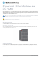
Installation and configuration of
the Vodafone MachineLink 3G
Powering the router
The MachineLink 3G Router can be powered in one of three ways:
1.
Power over Ethernet (802.3af PoE)
2.
DC power input via 2-pin connector (8-35V DC)
3.
DC power input via field terminated power source (8-35V DC)
4.
The green power LED on the router lights up when a power source is connected.
Power over Ethernet (802.3af PoE)
Power over Ethernet (PoE) is a method of connecting network devices through Ethernet cable where power and data are passed
along a single cable. This may be a desirable method of powering the device if PoE is available, or if it’s most convenient in the
desired installation environment to only have a single cable running to the MachineLink 3G device.
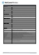
There are 5 power classes defined in the IEEE 802.3-2005 standard, of which the Vodafone MachineLink 3G is a class 3 device.
CLASS
CLASSIFICATION
CURRENT
POWER RANGE CLASS DESCRIPTION
3 26-30 mA 6.49 – 12.95 W Mid power
Table 6 - PoE power classes
To use PoE to power the MachineLink 3G, simply connect your router to a PoE injector or PoE network switch using the bundled
yellow Ethernet cable 8P8C.
DC power via 2-pin connector
The DC input jack can accept power from a separately sold DC power supply. Both a standard temperature range DC power
supply and an extended temperature range DC power supply are available to purchase as accessories.
To power the device via DC Power via the 2-pin connector, remove the attached green terminal block from your router and connect
the external DC power supply to the router’s green DC power jack.
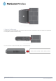
DC power via field terminated power source
If an existing 8-35V DC power supply is available, you can insert the wires into the supplied terminal block to power your router. Use
a No. 3 flathead screwdriver to tighten the terminal block screws and secure the power wires, making sure the polarity of the wires
are correctly matched, as illustrated below.
Figure 14 - Locking Power Terminal Block
PIN SIGNAL DESCRIPTION
+ V+ Voltage +
- V- Ground
Table 7 - Locking power block pin outs