NETCOMM CALLDIRECT™ SERIES – NTC C-6000 Series NE ETCOMM C CALLDIREC CT SERIES Rout NTC-6000 Series USSER GUID G E Prefac P ce
NETCOMM CALLDIRECT™ SERIES – NTC C-6000 Series This manual provides infoormation relating to the installation, operaation, and applicationn of this device. The individual reading thiss manual is presumeed to have a basic unnderstanding of teleccommunications term minology and concepts. If you find the product to be broken or malfunnctioning, please contact technical suppoort for immediate servvice by email at Technical.Support@netcoommwireless.
Table of Contents Introduction ......................................................................................................................................... 5 Overview ...................................................................................................................................................................................................................................................................................................................................
NETCOMM CALLDIRECT™ SERIES – NTC-6000 Series Contact ............................................................................................................................................. 78 NTC-6000 Series – Industrial M2M Wireless Routers 4 www.netcommwireless.
Introduction Thank you for purchasing an Industrial HSPA Cellular Network Router from NetComm. This manual illustrates how to set-up and configure your router appropriately for your chosen task. The router is primarily managed and configured via a web browser. This manual will take you through the steps required to configure and use your unit correctly. Additionally, the router may be configured via the serial (V.24) port using “AT” (V.250) commands.
NETCOMM CALLDIRECT™ SERIES – NTC-6000 Series Features Intelligent industrial cellular router platform supporting various networks and service types UMTS/HSDPA/HSUPA & GSM/GPRS/EDGE High-speed Atmel 400MHz ARM9-based Microcontroller. Embedded Sierra HSPA modem module MC8790V (NTC-6908) or MC8792V (NTC-6909) with Qualcomm MSM6290 chipset. Antenna diversity to improve fringe performance on global HSPA networks. Wide area data access speeds in 3G mode up to 7.2Mbps in downlink (HSDPA category 8) and up to 5.
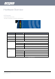
Hardware Overview LED Overview There are a total of five LED’s on the router. Listed below are the specifications of the LED’s and their corresponding colours. Figure 1: NTC‐6000 Series LEDs LED DISPLAY DESCRIPTION POWER (red) Solid ON The red Power LED indicates power has been applied to the router from the DC power input jack. TX Rx (amber) Solid ON The amber LED will light upon data being sent to or received from the cellular network.
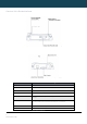
NETCOMM CALLDIRECT™ SERIES – NTC C-6000 Series Ovverview of the Routerr Interfacess Figure 2: Router Interfacess – Left Side View Figure 3: Router Interfaces – Right Side View FIELD DESCRIPTIO ON Main Anntenna Socket Female SMA Connectoor Receivee Diversity Antenna Socket Female SMA Connectoor Serial RS-232 Port For connecting to a teerminal using a DB9-F cable.
YML6908 www.netcommwireless.
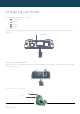
NETCOMM CALLDIRECT™ SERIES – NTC C-6000 Series Config C guringg yourr Routter You will need the followinng hardware componnents to set up the router: Power supply (8-28VDC) Ethernnet cable Laptoop or PC Activee SIM card Inseerting the SIM CCard Presss the SIM ‘Eject’ buttton to eject SIM card bay.
YML6908 www.netcommwireless.
NETCOMM CALLDIRECT™ SERIES – NTC-6000 Series Preparing Your Computer Connect one end of the supplied Ethernet cable to the Ethernet port of your router. Connect the other end of the cable to the LAN port of your computer. Configure your PC’s Ethernet interface to use a dynamically assigned IP address by completing one the following steps that correspond to the operating system your computer has installed.
Ethernet Interface Configuration inn Windows Vistaa T select “Control Panel” P followed by “NNetwork and Sharing Centre”. Click on the Start button. Then Figure F 6: Windows Vista V Control Panel Manage network connnections” to continuee. In the Manage network connections, click on “M Figure 7: W Windows Vista ‐Nettwork and Sharing Center C Singlee RIGHT click on “Local Area connection””, then click “Propertiies”.
NETCOMM CALLDIRECT™ SERIES – NTC C-6000 Series d click on “Intern rnet Protocol Version 4 (TCP/IPv4)”. The screen will display thhe information “User Account Control” annd click “Continue” too continue and then double Figure 9: Doouble Click Internet Protocol Version 4 (TCP/IPv4) Select “Obtain an IP addreess automatically” annd “Obtain DNS serveer address automaticcally” before clicking on the “OK” button to continue.
Ethernet Interface Configuration inn Windows 7 s the “Control Paanel (in Category Vieww)” option and then click c on the “View Network Status and Tassks”. Click on the Start button, select Figure 11 1: Windows 7 Contro ol Panel w select the “Change Adapter Settinngs” option to continue. In the “Network Settings” window Figure 12: Window ws 7 Network and Sharing Center Singlee RIGHT click on “Local Area Connection”, then click “Propertties”.
NETCOMM CALLDIRECT™ SERIES – NTC C-6000 Series P Version 4 (TCCP/IPv4)”. Double click on “Internet Protocol Figure 14: Doouble Click Internett Protocol Version 4 (TCP/IPv4) a “Obtain DNS serrver address automatically” then click on “OK” to continue. Click on “Obtain an IP adddress automatically” and Figure 15: Set Prop perties to Automatiic Settings Click on “OK” to complete the computer prepparation for the routerr. NTCC-6000 Series – Indusstrial M2M Wireless Routers R 16 wwww.netcommwireless.
Acccessing thhe Router Web W User Interface Therre are two system maanagement accounts for maintaining the system, s root and admmin, which both have slightly different routter management cappabilities. The root manager account is has full permission privileges and caan use every commannd option that the rouuter is configured with. ministrator) account has h access to the maajority of router settinggs available except the t router’s system options that can alter oor copy the router’s firmware f (software).
NETCOMM CALLDIRECT™ SERIES – NTC C-6000 Series Unnlocking thhe SIM Carrd w assigned to you r SIM card by your mobile m broadband proovider. To check if thhe SIM card is lockedd view the SIM Status on If thee SIM card is locked it can only be unlockked using a PIN that was the router r Status page: Figure 119: SIM Status Lockked s above, you shhould be automaticallly redirected to the SIM S unlock page.
YML6908 www.netcommwireless.
NETCOMM CALLDIRECT™ SERIES – NTC-6000 Series Enter PUK Code If after three incorrect attempts at entering the PIN code, you will be requested to enter a PUK code. Figure 24: Enter Correct PIN and PUK Message The PUK code is sometimes referred to as a PIN Unlocked Key (PUK) code. You will need to contact your mobile broadband provider to obtain this number. Your mobile broadband provider will issue you a PUK code which will enable you to unlock the SIM card and enter a new PIN code.
The ‘Remember PIN’ Feature This feature allows the router to automatically send the PIN to the SIM each time the SIM asks for it (usually at power up). This enables the SIM to be PIN Locked (to prevent unauthorized use of the SIM card elsewhere), while still allowing the router to connect to the cellular service. When this feature is enabled the PIN entered by the user when they set the “Remember PIN” feature is encrypted and stored locally in the router.
NETCOMM CALLDIRECT™ SERIES – NTC C-6000 Series Ceellular Bandd and MBBB Provider Selection Loccking To a Speccific Band You may want to lock thee router to a specific band. To do this, clicck on the “Internet Seettings” menu and select “Mobile Broadbaand” followed by the “Band / Provider” meenu item on the right.. You may want to do this iif you’re using the rouuter in a country with multi frequency netwworks that may not all support HSPA.
BAND SELEECTION OPTIONS – NTC-6909 UMTS 9000Mhz Only UMTS 9000 MHz Only WCDMA All A UMTS 900/22100/1900MHz UMTS 9000MHz, 2G UMTS 900 MMHz GSM/EDGE/GPRS 8550/900/1800/1900MHz 2G GSM/EDGEE/GPRS 850/900/1800/19000MHz ALL BANDDS (AUTOBAND) UMTS 8500/900/2100/1900MHz GSM M/EDGE/GPRS Table 7: NTC‐69009 Band Selection Options O Click Save to confirm the new n band settings.
NETCOMM CALLDIRECT™ SERIES – NTC-6000 Series Establishing a Connection to a Cellular Network This section describes how to configure the router to initiate a Mobile Broadband connection. There are 2 possible methods that can be used to set up a Mobile Broadband connection via PPP: Initiating the PPP Connection directly from the router (most common). Initiating the PPP Connection from a different PPP client (i.e. laptop or router) with the router running in transparent PPPoE mode.
Connnecting to the Internet using a Connection Proofile The router supports multiiple APN profiles; thaat allow you the router settings to be confi gured to connect to different cellular netw works Figure 34: Mobille Broadband ‐ Conn nection Page First eexamine the list of configured profiles Select the profile that you wish to connect with and make sure that the APN name field is correct. This is veryy important Select “Enable” for the Autto Connect option annd click Save.
NETCOMM CALLDIRECT™ SERIES – NTC C-6000 Series Initiiating a Connecction using the Router R in Transpparent PPPoE moode To enable PPPoE mode, ensure the “Auto Connect” option is disabled in each of the pprofiles on the “Conneection” configuration page. To check this click on the “Internet Settings” menu, theen selecct “Mobile Broadband” followed by the “CConnection” menu iteem. Select each connnection profile and disable the Auto Connection option and sav ave the updated settinngs.
Ethernet Related Commands How to configure the Ethernet IP address The IP settings can be configured by clicking on the “Internet Settings” menu followed by “LAN” and then “IP Setup” The default IP of the Ethernet port is 192.168.20.1 with the subnet mask 255.255.255.0. If you wish to change this then simply enter the new IP address and click on the Save button at the bottom of the page.
NETCOMM CALLDIRECT™ SERIES – NTC-6000 Series If you do not enter the DNS1 and DNS2 addresses manually, then to browse the Internet from your Ethernet connected device you must enable DNS Masquerade (see above). Upon enabling DNS Masquerade, you will notice that the DNS1 address is automatically set to the IP address of the Ethernet port. DNS addresses are then automatically assigned by the connection to the network.
Virrtual Privatte Networks A Virrtual Private Network (VPN) is a tunnel prooviding a private link between two networrks or devices over a public network. Dataa to be sent via a VPNN needs to be encappsulated and as suchh is geneerally not visible to puublic network. mon encapsulation methods m used to create a virtual private neetwork (VPN) over public networks. OpenVVPN and IPSec can aalso be configured on the NTC-6000 seriees PPTPP and GRE are comm routeers.
NETCOMM CALLDIRECT™ SERIES – NTC C-6000 Series Therre are a few configuraation steps you will need to complete before obtaining a PPTPP/GRE connection: Step 1: Connect too the Cellular Brooadband Netwoork: Click on the “Internet Settings” menu followed by “Mobile Broadbannd” and then the “Coonnection” menu item on the right and in ththe Mobile Broadband Profile Settings secction, click ‘‘enable’ for the approopriate profile. c on the Status m menu at the top of the page and check the WWAN status.
OppenVPN m for creating point-too-point or server-to-m multi-client encryptedd tunnels between hoost computers. The NTC-6000 supports thhree OpenVPN is an open souurce virtual private neetwork (VPN) program different OpenVPN modees: OppenVPN Server OppenVPN Client OppenVPN Peer-to-Peer VPN connection. Figure 43: Interneet Settings ‐ OpenV VPN YMLL6908 wwww.netcommwireless.
NETCOMM CALLDIRECT™ SERIES – NTC-6000 Series DEFINITION ITEM Profile Type Set this option to OpenVPN to create an OPenVPN VPN tunnel. Enable VPN Enable or Disable the VPN connection. Profile Name A name that can be used to identify the VPN connection. OpenVPN Type Server Port VPN Network Address VPN Network Mask Diffie-Hellman parameters Select the type of OpenVPN session to use. Options include Server, Client or Peer-to-Peer Enter the port number the OpenVPN connection is to run on.
IPSSec a as such can prottect higher layer prottocols. IPSec is used for both Site to Site VPN V and Remote Acccess VPN. The NTC-6000 Series Cellular IPSeec operates on Layerr 3 of the OSI model and routeers support IPsec end points and can be configured with Site to Site VPN tunnels wwith other NTC-6000ss or third party VPN routers. r mmwireless.com/prodduct/m2m/ntc-6000 A White Paper with full Innstructions on configuuring an IPSec VPN tunnel is available at http://support.
NETCOMM CALLDIRECT™ SERIES – NTC-6000 Series DEFINITION ITEM Profile Type Set this option to IPSec. Enable VPN Enable or Disable the VPN connection. Profile Name A name that can be used to identify the VPN connection. Remote IPSec Gateway Road Warrior The IP address that the IPSec server is running on. Click this to configure the VPN connection for Road Warrior (connection from a dynamic IP Address) use.
Roouting Configuration Connfiguring Static Routes This facility is available bby clicking on the “Intternet Settings” beforre selecting “Routing ” followed by the “Staatic” menu item on thhe right. me routes are added bby the router automatically on a connectioon initialization such aas the Ethernet subnnet route for routing too a device on an Etheernet subnet. A PPP route is also added upon u Som obtaaining a WAN PPP coonnection. a some more static routes.
NETCOMM CALLDIRECT™ SERIES – NTC C-6000 Series Deleting Static Rouutes Figure 47: Delleting a Static Routee Entry Select the “Delete Entry” text (in blue) for the route as shown in thee figure above. Hoow to Conffigure RIP r routing table will be advertised to other nearby routerss. RIP (Routing Information Protocol) is used forr advertising routes too other routers.
Hoow to Conffigure VRRP The Virtual Router Redunndancy Protocol (VRRRP) is a non-proprietaary redundancy protoocol designed to incrrease the availability and reliability of the ddefault gateway servvicing hosts on the saame subnnet. This increased reeliability is achieved by advertising a “virtual router” (an abstraact representation of master and backup routers acting as a ggroup) as a default gaateway to the host(s) insteead of one physical roouter.
NETCOMM CALLDIRECT™ SERIES – NTC C-6000 Series NAAT configuration This facility is available bby clicking on the “Intternet Settings” menuu followed by “Routinng” and then the “NATT” menu item on the right. The router is seet to use NAT mode by b default. With NAT enabbled by default port fforwarding may be neecessary to use somee applications and d evices over the internet.
Howw to Configure DDMZ The Demilitarized Zone (DMZ) enables a device to utilize a direct connection to the WAAN. This means any incoming connectionns are forwarded direectly to this device with all ports open. This facility is available bby clicking on the “Intternet Settings” menuu followed by “Routinng” and then the “DMZ” menu item on the right. Figure 52: Internnet Settings ‐ Routin ng ‐ NAT Services Feaatures YMLL6908 wwww.netcommwireless.
NETCOMM CALLDIRECT™ SERIES – NTC C-6000 Series Seervices Feaatures Howw to Configure tthe Dynamic DNNS Client This facility is available bby clicking on the “Seervices” menu followeed by the “DDNS” meenu item on the right. Dynaamic DNS provides a method for the routeer to update an exterrnal name server withh the current WAN IP address. To configure dynamic DNSS set the DDNS Conffiguration option to Ennable. s that you wish to use. Enter your dyynamic DNS accountt credentials.
SNM MP Traps The SNMP Trap functionss to provide system event e notifications to a SNMP server withoout solicitation so that the SNMP server dooes have to request iinformation from each and every device work traffic and resouurces connnected on the networrk.
NETCOMM CALLDIRECT™ SERIES – NTC C-6000 Series Howw to Configure tthe Periodic Ping Reset Monitorr This facility is available bby clicking on the “Seervices” menu followeed by the “System Moonitor” menu item on the right. c ping packe kets to 1 or 2 user speecified IP addresses. Should the router noot receive responses to the pings, the rouuter The Periodic Ping Reset Monitor configures thhe router to transmit controlled r will reboot. This works as follows: Figure 57: Services ‐ System m Monitor 1.
Perriodic Ping Disabled To disable d the Periodic PPing Reset Monitor sim mply set to “Fail Count” 0 Figure 58: Services ‐ System Monito or Perriodic Ping Enabbled E Setup: An Example m if it fails it theen tries to ping 10.1.22.4, if that also fails it then accelerates thee ping attempts to onnce every 60 secondss and if 3 successivee ping The setup below will pingg 10.1.2.3 every 10 minutes, mpts at the one minute interval fails, the roouter will reboot.
NETCOMM CALLDIRECT™ SERIES – NTC C-6000 Series Howw to Configure a Periodic Reset Timer This facility is available bby clicking on the “Seervices” menu followeed by the “System Moonitor” menu item on the right. The router can be configured to automaticallyy reboot after a perioddic interval specifiedd in minutes. While this is not necessary, itt does ensure that in the case of remote installations, the routeer will rebooot if some anomaly ooccurs.
GPPS This facility is available bby clicking on the “Seervices” menu followeed by the “GPS” mennu item on the right. The built-in GPS module enables you to utilizee location based servvices, keep track of hhardware out in the field or find your curreent location.
NETCOMM CALLDIRECT™ SERIES – NTC C-6000 Series SM MS Tools S functionality succh as sending a messsage, receiving a message and redirectinng an incoming message to another destinnation. The SMS tools applicatioon has been developeed to include basic SMS a change run-time variables on the routter. You can also utilize this ffunctionality to read and Basic functionality suppoorted: Abilityy to send a text messsage via a 3G network and store in permaanent storage.
SMS Configurationn for Redirection Incoming text messages can be redirected too another mobile device and/or a TCP/UDDP message server. Red direct to Mobilee You can forward incominng text messages to a different destinationn number. This destinnation number can be another mobile phoone or 3G router phoone number. To disabble the feature, simplyy delete the number in the ‘Redirect to Mobile” field and click the “SSave” button.
NETCOMM CALLDIRECT™ SERIES – NTC C-6000 Series SMS - New Messagge The New Message page can be used to sendd an SMS text messages to one or multipl e recipients. Figure 65: Servicces ‐ SMS ‐ New Messsage mum of 100 recipientss at the same time. Affter sending the message, the result is dissplayed next to the ddestination number ass “Success” (in blue) or A neew SMS message cann be sent to a maxim “Failure” (in red).
Inbox/Outbox You can check all sent SMS messages in the SMS Outbox or you can read, delete, reply or forward an SMS message to another mobile device from the SMS Inbox. You are also able to add the SMS message sender to the “White List” which is used to secure the Remote Diagnostics feature. Simply select the sender or recipient number and click the “Add White List” button. Figure 66: Services ‐ SMS ‐ Inbox Figure 67: Services ‐ SMS ‐ Outbox YML6908 www.netcommwireless.
NETCOMM CALLDIRECT™ SERIES – NTC C-6000 Series SMS Diagnostics aand Command Execution E Setupp Figure 68: Servicces ‐ SMS – Diagnostics and command Execution E Setup Enaable Authenticaation Enabble or disable checking the sender’s phonne number against thhe allowed sender “W White List” for incominng Diagnostics/Comm mand Execution SMSS messages. White List”.
Fix xed Ack. SMS N Number Acknnowledgement messages sent after the execution of a “Set” command will be sentt to this number. Sen nd Error SMS ffor Get/Set/Execc Command Enabble or disable the sennding of an error messsage resulting from the execution of a G et/Set/Exec commannd. If dissabled, the router does not send any erroor notifications after thhe execution of a Gett/Set/Exec command. This function is disabled by default. Sen nd Error SMS too f the execution off a Get/Set/Exec commmand.
NETCOMM CALLDIRECT™ SERIES – NTC-6000 Series White List A maximum number of 20 entries can be stored in the router. If Authentication is enabled, any incoming Diagnostics/Command Execution SMS messages are processed only if the sender’s number exists in White List and the message password matches with the password specified in the White List. One blank entry is shown by default and you can add or delete an entry by pressing the “+” or “–“ button.
SMS Command format Generic Format for reading variables: get VARIABLENAME PASSWORD get VARIABLENAME Generic Format for writing to variables: set VARIABLENAME=VALUE PASSWORD set VARIABLENAME=VALUE Generic Format for executing a command: execute COMMAND PASSWORD execute COMMAND Replies Upon receipt of successfully formatted, authenticated (if required) command, the router will reply to the SMS in the following format: SMS CONTENTS TYPE Get Command “VARIABLENAME=VALUE” Set Command “Successfully set VARIA
NETCOMM CALLDIRECT™ SERIES – NTC-6000 Series If the command sent includes the “reboot” command and has already passed the White List password check, the device keeps this password and executes the remaining command line after the reboot with this same password. For Example: xi. “PASSWORD execute reboot; get Variable1”; “get VARABLE2” xii. “PASSWORD execute reboot; PASSWORD get Variable1”; “get VARABLE2” Commands are case insensitive; however variable names and values are case sensitive.
List of Valid Variables: Where “x” is a profile number (1-6). If no profile is specified, variables are read for or written to for the current active profile. If a profile is specified, the variable is read for or written to for the specified profile number (‘x’). # SMS VARIABLE NAME RDB VARIABLE NAME READ/WRITE DESCRIPTION Profile link.profile.x.enable Read: link.profile.x.apn (profile no,apn,user,pass,auth,iplocal,status) link.profile.x.user profile 1,Telstra.
NETCOMM CALLDIRECT™ SERIES – NTC-6000 Series SMS Diagnostics Examples The examples below demonstrate various combinations of supported commands. This is not a complete list. To obtain a complete list, please contact NetComm. DESCRIPTION INPUT EXAMPLE AUTHENTICATION set apn1=Telstra.internet Not Required set apn2=”3netaccecss” Send SMS to change APN Required Password1234 set apn1=Telstra.
NSSUpdate U is used to update an internal DNSS resource. This can be b used to enable a ffully qualified domainn name (FQDN) to bee used to access thee router. NS Update Figure 69: Serrvices ‐ NSUpdate FIELD DESCRIPTION N Server Address The server adddress is the name server too which updates will be sennt to. Secondary Server Adddress The secondaryy server address is a backuup name server to which updates will be sent to. DNS Zone Specify the DNNS domain to be updated.
NETCOMM CALLDIRECT™ SERIES – NTC C-6000 Series System S m Feaaturess Vieewing the ssystem logg This facility is available bby clicking on the “Syystem” menu followedd by “Log“. Figure 70: System m Log Page The System Log enabless you to troubleshoot any issues you may be experiencing withh your router. Selecting the appropriatee logging level will shhow you either informational messages abbout your router or evvery message producced when “All” is seleected.
Reemote Adm ministration This facility is available bby clicking on the “Syystem” menu followedd by “Administration” . Once Remote administraation is enabled, you are able to access thhe router’s web-baseed configuration pagees from a remote locaation to make configuuration changes and to enable or disable featuures. g remote access, yoou have to connect too the WAN IP address of the router on thee port assigned in thee configuration page (e.g.
NETCOMM CALLDIRECT™ SERIES – NTC C-6000 Series Note: Youu can find the router’ss WAN IP address byy clicking on the “Stattus” menu. The Locaal field in the WWAN section s shows the rouuter’s WAN IP addresss. 3. Click “Login” and type “admin” or “rooot” in the Username and “admin” in the Paassword fields (withouut quotes). Then clickk on the “Submit” buttton.
Reestoring a CCopy of thee Router’s Configurattion This facility is available bby clicking on the “Syystem” menu followedd by “Load / Save” annd then the “Settings” menu item on the right. Click Browse. Select the configuration file you wish to restore. Click Restore.
NETCOMM CALLDIRECT™ SERIES – NTC C-6000 Series Loocal Firmwaare Upgradde The firmware update process has two steps. The first step is to uppload and install the ssystem recovery image onto the router. y computer. You can do this by clickinng on the browse button and then to navigate to where the reccovery image upgradde file is located on your Figure 76: System m ‐ Load/Save ‐ Uplload u has finished when w Once you have selected the system recoveryy image file to use, click Upload to uploadd the file.
The second step is to upload and install the main system software image. To do this, open your web browser (e.g. Internet Explorer/Firefox/Safari) and navigate to http://192.168.20.1/ Click “Login” and type “root” in the Username and “admin” in the Password fields (without quotes). Then click on “Submit”. The banner at the top of the page should now be different to show that the router is currently in recovery console mode.
NETCOMM CALLDIRECT™ SERIES – NTC C-6000 Series Reemote Firm mware Upgrade The remote firmware upddate process has twoo steps: 1. Upload and installl the system recoveryy image to the router. 2. Upload and installl the main system imaage to the router. Note: Do not interrupt the powwer during a remote firmware upgrade, ass this may render the router unable to start up and will require a local system recovvery upload to be performedd.
Figure 90: System m ‐ Load/Save ‐ Uplload Firmware U to upload thee file. You will then see a progress bar as shown s in the screensshot below. The upload has finished whenn the Once you have selected the main system imaage file to use, click Upload % and the “Phase:” haas changed to Complete. statuus bar reaches 100% mpleted, the screen should refresh and list the file you have juust uploaded. Click on o the “Install” link to the right of this. Wheen the upload has com ected Internet servicee.
NETCOMM CALLDIRECT™ SERIES – NTC C-6000 Series Syystem Conffiguration The System configurationn page is used to speecify an external syslog server and the TCCP Keepalive settingss. WAN connection does not become disconnnect due to inactivity by periodically sending a ping request message to a WAN IP address or domainn to TCP Keepalive can be ussed to ensure the WW conffirm the network connnection is still valid.
TRR-069 ment Protocol (CWMPP). It is a framework fofor remote management and autoThe TR-069 (Technical RReport 069) protocol is a technical specificcation also known as CPE WAN Managem conffiguration of end-userr devices such as customer-premises equuipment (CPE) and AAuto Configuration Seervers (ACS). It is parrticularly efficient in aapplying configuration updates across netwworks to multiple CPEEs. w TR-0069 uses a bi-directioonal SOAP/HTTP-bassed protocol based on the application layeer protocol.
NETCOMM CALLDIRECT™ SERIES – NTC C-6000 Series Loggoff The logoff item will log yoou out of your web coonfiguration session. Fiigure 95: System ‐ Logoff L Rebboot The reboot item will reboot the router. This caan be useful if you havve made configuratioon changes you wantt to implement or wannt to reboot the routeer. Figure 96: Systeem ‐ Reboot NTCC-6000 Series – Indusstrial M2M Wireless Routers R 68 wwww.netcommwireless.
Trouble T eshoooting Common C prroblems annd solutionns. 1. I cannot seem too access the web pagge interface. o a web browserr to this address. Alsoo check that your laptop/PC is on the samme subnet as the router’s Ethernet port if you y The default IP address off the router is 192.168.20.1, so first try to open u a static IP addrress. are using 2. The router was coonnected but cannot get g back online. mer using the System Monitor (Click on thee “Services” menu foollowed by “System Monitor”).
NETCOMM CALLDIRECT™ SERIES – NTC-6000 Series If a SIM was installed correctly this may indicate that the SIM has been removed or inserted whilst the unit is powered up. In this case you must reboot the unit. To reboot the router, click on the “System” menu followed by “Reboot“. Clicking the reboot button on this page will reboot the router. NTC-6000 Series – Industrial M2M Wireless Routers 70 www.netcommwireless.
8. I am having problems getting a PPTP connection. Check the routes on the “Routing” configuration page (This facility is available by clicking on the “Internet Settings” menu followed by “Routing” and then the “Static” menu item on the right.) i. There should be 5 routes shown. ii. One route for interface eth0. iii. Two routes for interface ppp0. iv. Two routes for interface ppp1. If there are not 5 routes, it is possible the one of the following conditions exist: i. PPTP is not enabled. ii.
NETCOMM CALLDIRECT™ SERIES – NTC-6000 Series Specifications Hardware Specifications NTC-6908 MCU / Processor Atmel AT91SAM9G20 Microcontroller / ARM9 based RAM 32MB DRAM Memory 256MB NAND Flash Sierra Wireless MC8790V Wireless WAN Interface Chipset NTC-6909 NTC-6900 Sierra Wireless MC8792V Sierra Wireless MC8795V 900/ 1900/ 2100 MHz 850/ 900/ 1900/ 2100 MHz Qualcomm MSM6290 850/ 1900/ 2100 MHz 3G UMTS Bands 850/ 900/ 1800/ 1900 MHz 2G GSM Bands HSDPA Category 8 – Downlink up to 7.
RJ--45 Ethernet Porrt Integration Paarameters You can use the guide beelow to design Ethernet cables to integrate the router into youur systems.
NETCOMM CALLDIRECT™ SERIES – NTC-6000 Series Custom Application and Scripting The NTC series router covered in this manual offers the ability for the user to install custom application and firmware images via the application programming interface. For further information, please contact the NetComm M2M support team. CONTACT Phone DETAILS +61 (02) 9424 2053 Fax 1800 063 962 Email service@call-direct.com.au Web www.netcommwireless.
Legal & Regulatory Information Intellectual Property Rights All intellectual property rights (including copyright and trade mark rights) subsisting in, relating to or arising out this Manual are owned by and vest in NetComm Wireless (ACN 002490486) (NetComm Wireless Limited) (or its licensors). This Manual does not transfer any right, title or interest in NetComm Wireless Limited’s (or its licensors’) intellectual property rights to you.
NETCOMM CALLDIRECT™ SERIES – NTC-6000 Series Product Warranty All NetComm Wireless products have a standard one (1) year warranty from date of purchase, however, some products have an extended warranty option (refer to packaging and the warranty card) (each a Product Warranty).
instructions, may cause harmful interference to radio communications. However, there is no guarantee that interference will not occur in a particular installation If this equipment does cause harmful interference to radio or television reception, which can be determined by turning the equipment off and on, the user is encouraged to try to correct the interference by one or more of the following measures: -Reorient or relocate the receiving antenna.
NETCOMM CALLDIRECT™ SERIES – NTC-6000 Series Contact Address: NETCOMM WIRELESS LIMITED Head Office PO Box 1200, Lane Cove NSW 2066 Australia Phone: +61(0)2 9424 2070 Fax: +61(0)2 9424 2010 Email: sales@netcommwireless.com techsupport@netcommwireless.com NTC-6000 Series – Industrial M2M Wireless Routers 78 www.netcommwireless.