
User's Manual

www.netcommwireless.com
NetComm Wireless 3G M2M Router / Plus
17
NTC-6200-01, NTC-6200-02, NTC-6200-11 and NTC-6200-12
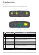
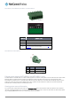
Figure 12 – Locking Six-way Power Terminal Block
Figure 13 – Terminal block connector
TERMINAL
DESCRIPTION
+
Positive wire for power.
-
Ground wire.
i
Dedicated terminal for ignition detection.
I/O
Three terminals used for input/output detection (refer to the IO
configuration section for more information).
Table 9 - Locking power block pin outs
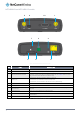
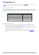
NTC-6200-03 and NTC-6200-13
Figure 14 – Locking Two-way Power Terminal Block
PIN
SIGNAL
DESCRIPTION
+
V+
Voltage +
-
V-
Ground
Table 10 - Locking power block pin outs
Failover power support (NTC-6200-01 and NTC-6200-11 only)
The NTC-6200-01 and NTC-6200-11 routers include support for connection of two power sources at the same time. When a PoE
Ethernet cable is connected and DC power is also supplied to the DC input jack of the router, the router will source power
exclusively from the PoE source. In the event that power from the PoE cable is lost, the router will automatically switch to source
power from the DC input jack, without affecting the router’s operation. When PoE power is restored, the router automatically
switches back to receive power from the PoE input source.
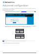
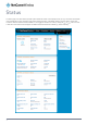
Viewing power source information
You can view the current power input mode in the Advanced status section of the device’s web user interface. This is useful for
remotely monitoring the device. You can also use the Software Development Kit to access this information for advanced purposes
(e.g. configuring SMS alerts to inform you of the power status of the router).