
User's Manual


www.netcommwireless.com
NetComm Wireless 3G M2M Router / Plus
127
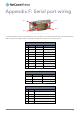
Appendix F: Serial port wiring
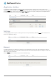
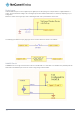
Figure 130 - DE9 Male connector (Pin side view)
The NTC-6200 Series router has a serial interface and acts as the data communications equipment (DCE). The wiring tables below
reflect the DCE device. Shielding cable can optionally be soldered to the chassis and connected to ground.
RS-232 WIRING
PIN
NAME
DIRECTION
DESCRIPTION
1
DCD
IN
Data carrier detect
2
RXD
OUT
Receive Data
3
TXD
IN
Transmit Data
4
DTR
OUT
Data Terminal Ready
5
GND
-
Ground
6
DSR
IN
Data Set Ready
7
RTS
OUT
Request to Send
8
CTS
IN
Clear to Send
9
RI
IN
Ring Indicator
Table 38 - RS-232 Wiring
RS-485 HALF DUPLEX WIRING
PIN
NAME
DESCRIPTION
1
A
Differential pair A
2
B
Differential pair B
5
GND
Ground
Table 39 - RS-485 Half Duplex Wiring
RS-485 (RS-422) FULL DUPLEX WIRING
PIN
NAME
DESCRIPTION
1
RXA
Receive (Differential pair A)
2
RXB
Receive (Differential pair B)
3
TXB
Transmit (Differential pair B)
4
TXA
Transmit (Differential pair A)
5
GND
Ground
Table 40 - RS-485 (RS-422) Full Duplex Wiring
Pin 9
Pin 6
Pin 5
Pin 1