
User's Manual

12
NetComm Wireless 3G M2M Router / Plus
www.netcommwireless.com
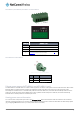
NTC-6200-03 and NTC-6200-13 models
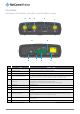
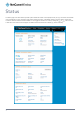
Figure 5 - Interfaces NTC-6200-03 and NTC-6200-13 models
NO.
ITEM
DESCRIPTION
1
Main antenna socket
SMA female connector for main antenna.
2
Aux antenna socket
SMA female connector for auxiliary antenna (receive diversity).
3
Two-way terminal block connector
Connect power source wires here. Power wires may be terminated on the supplied terminal block and
connected to a power source. Refer to the diagram and table under the Installation section for correct
wiring of the terminal block. Operates in the 8-40V DC range.
4
Reset button
Press and hold for less than 5 seconds to reboot to normal mode.
Press and hold for 5 to 15 seconds to reboot to recovery mode.
Press and hold for 15 to 20 seconds to reset the router to factory default settings.
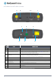
5
SIM card slot
Insert SIM card here.
6
SIM tray eject button
Press to eject the SIM tray
7
Torx screw hole
If desired, place the SIM tray cover over the SIM card slot and fix it to the router’s body using the included
Torx screw.
8
RJ45 Ethernet port
Connect one or several devices via a network switch here.
9
Mini USB 2.0 OTG port
Provides connectivity for optional external storage or a USB Ethernet dongle. Supplies up to 0.5A to
connected device.
10
Serial port
Female DB9 port supporting 9-wire RS-232, RS-485 or RS-422 (software selectable).
Table 7 – Interfaces NTC-6200-03 and NTC-6200-13 models
1
2
3
4
5
6
7
8
9
10