User Guide NTC-6200 Series – 3G M2M Router / Plus
Copyright Copyright© 2014 NetComm Wireless Limited. All rights reserved. The information contained herein is proprietary to NetComm Wireless. No part of this document may be translated, transcribed, reproduced, in any form, or by any means without prior written consent of NetComm Wireless. Note: This document is subject to change without notice.
Table of Contents Overview ........................................................................................................................................................................................ 5 Introduction ................................................................................................................................................................................................... 5 Target audience........................................................................
Technical Data ........................................................................................................................................................................... 133 Safety and product care ............................................................................................................................................................ 136 Product Warranty........................................................................................................................
Overview Introduction This document provides you all the information you need to set up, configure and use the NetComm Wireless NTC-6200 Series router. Target audience This document is intended for system integrators or experienced hardware installers who understand telecommunications terminology and concepts. Prerequisites Before continuing with the installation of your NTC-6200 Series router, please confirm that have the following: A device with a working Ethernet network adapter.
Product introduction Product overview Penta-band 3G with quad-band 2G auto-fallback HSPA+ up to 14.4 Mbps DL Ethernet port with full passive Power over Ethernet (PoE) support (802.3af) (NTC-6200-01 and NTC-6200-11 only) RS232/RS422/RS485 Port and USB 2.
Product features The NetComm Wireless NTC-6200 Series router is an M2M device designed by NetComm Wireless to address the rapid growth in M2M deployments. It has been designed to provide state-of-the-art features and versatility at an affordable price. Compatible with networks worldwide, the NTC-6200 Series router can be managed remotely even when it does not have an Internet connection via the use of SMS diagnostics and commands.
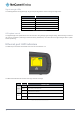
Physical dimensions and indicators Physical dimensions Below is a list of the physical dimensions of the NTC-6200 Series router. Figure 1 – NTC-6200 Series router Dimensions NTC-6200 SERIES ROUTER (WITHOUT EXTERNAL ANTENNAS ATTACHED) Length 143 mm Depth 107 mm Height 34 mm Weight 221g Table 2 - Device Dimensions NetComm Wireless 3G M2M Router / Plus 8 www.netcommwireless.
LED indicators The NTC-6200 Series router uses 8 LEDs to display the current system and connection status.
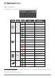
Signal strength LEDs The following table lists the signal strength range corresponding with the number of lit signal strength LEDs. NUMBER OF LIT LEDS SIGNAL STRENGTH All LEDs unlit < -109 dBm 1 -109 dBm to -101dBm 2 -101 dBm to -91 dBm 3 -91 dBm to -85 dBm 4 -85 dBm to -77 dBm 5 > -77 dBm Table 4 - Signal strength LED descriptions LED update interval The signal strength LEDs update within a few seconds with a rolling average signal strength reading.
Interfaces NTC-6200-01, NTC-6200-02, NTC-6200-11 and NTC-6200-12 models 2 10 3 11 8 1 5 1 6 7 4 9 Figure 4 - Interfaces - NTC-6200-01, NTC-6200-02, NTC-6200-11 and NTC-6200-12 models NO. ITEM DESCRIPTION 1 Main antenna socket SMA female connector for main antenna. 2 Aux antenna socket SMA female connector for auxiliary antenna (receive diversity). 3 GPS antenna socket SMA female connector for an active GPS antenna.
NTC-6200-03 and NTC-6200-13 models 2 9 10 7 5 3 1 4 6 8 Figure 5 - Interfaces NTC-6200-03 and NTC-6200-13 models NO. ITEM DESCRIPTION 1 Main antenna socket SMA female connector for main antenna. 2 Aux antenna socket SMA female connector for auxiliary antenna (receive diversity). 3 Two-way terminal block connector Connect power source wires here. Power wires may be terminated on the supplied terminal block and connected to a power source.
Placement of the router The two external high-performance antennas supplied with the router are designed to provide optimum signal strength in a wide range of environments. If you find the signal strength is weak, try adjusting the orientation of the antennas. If you are unable to get an acceptable signal, try moving the router to a different place or mounting it differently.
Wall mounted via DIN rail bracket Figure 8 - Wall mounted via DIN rail bracket DIN rail mount Figure 9 – DIN rail mount NetComm Wireless 3G M2M Router / Plus 14 www.netcommwireless.
Pole mount using DIN rail bracket Figure 10 - Pole mount using DIN rail bracket Desk mount Figure 11 – Desk mount www.netcommwireless.
Installation and configuration of the NTC-6200 Series router Powering the router The NTC-6200 Series router can be powered in one of three ways: 1. Power over Ethernet (802.3af PoE) (available on the NTC-6200-01 and NTC-6200-11 only) 2. DC power input via 6-pin or 2-pin connector (8-40V DC) 3. DC power input via field terminated power source (8-40V DC) The green power LED on the router lights up when a power source is connected. Power over Ethernet (802.
NTC-6200-01, NTC-6200-02, NTC-6200-11 and NTC-6200-12 Figure 12 – Locking Six-way Power Terminal Block Figure 13 – Terminal block connector TERMINAL DESCRIPTION + Positive wire for power. - Ground wire. i Dedicated terminal for ignition detection. I/O Three terminals used for input/output detection (refer to the IO configuration section for more information).
To view the router’s power source information, log in to the router and expand the Advanced status box on the status page. See the Status section of this manual for more information on the status page. Power consumption To assist with power consumption planning, the following table summarises average power consumption during the various states of the NTC-6200 Series router under normal usage conditions.
Advanced configuration The NTC-6200 Series router comes with pre-configured settings that should suit most customers. For advanced configuration, log in to the web-based user interface of the router. To log in to the web-based user interface: 1. Open a web browser (e.g. Internet Explorer, Firefox, Safari), type http://192.168.1.1 into the address bar and press Enter. The web-based user interface log in screen is displayed. Figure 15 – Log in prompt for the web-based user interface 2.
Status The status page of the web interface provides system related information and is displayed when you log in to the NTC-6200 Series router management console. The status page shows System information, LAN details, Cellular connection status, Packet data connection status and Advanced status details. You can toggle the sections from view by clicking the or buttons to show or hide them. Extra status boxes will appear as additional software features are enabled (e.g. VPN connectivity).
ITEM DEFINITION System information System up time The current uptime of the router. Board version The hardware version of the router. Serial Number The serial number of the router. Firmware version The firmware version of the router Model The type of phone module and the firmware version of the module. Module firmware The firmware revision of the phone module. IMEI The International Mobile Station Equipment Identity number used to uniquely identify a mobile device.
CID Cellular configuration ID Table 14 - Status page item details NetComm Wireless 3G M2M Router / Plus 22 www.netcommwireless.
Networking The Networking section provides configuration options for Wireless WAN, LAN, Routing and VPN connectivity. Data Connection The data connection page allows you to configure and enable/disable the connection profile. To access this page, click on the Networking menu, and under the Wireless WAN menu, select the Data connection item. Figure 17 – Data connection settings www.netcommwireless.
ITEM DEFINITION Data connection Transparent Bridge (PPPoE) Toggles the transparent bridge function on and off. Profile name list Default Sets the corresponding profile to be the default gateway for all outbound traffic except traffic for which there are configured static route rules or profile routing settings. Status Toggles the corresponding profile on and off. If your carrier supports it, two profiles may be turned on simultaneously. APN The APN configured for the corresponding profile.
2. Click the Profile toggle key to turn the profile on. Additional settings appear. Figure 19 - Data connection settings - Profile turned on 3. In the Profile name field, enter a name for the profile. This name is only used to identify the profile on the router. 4. Ensure that the Automatic APN selection toggle key is set to off. If it is not, click it to toggle it to the off position. 5.
12. For advanced networking such as using dual simultaneous PDP contexts, you may wish to configure a particular profile to route only certain traffic via that profile by configuring a custom address and mask of traffic to send via that profile. To do this, in the Profile routing settings section, enter the Network address and Network mask of the remote network.
Connect on Demand The connect on demand feature keeps the Packet Data Protocol (PDP) context deactivated by default while making it appear to locally connected devices that the router has a permanent connection to the mobile broadband network. When a packet of interest arrives or an SMS wake-up command is received, the router attempts to establish a mobile broadband data connection. When the data connection is established, the router monitors traffic and terminates the link when it is idle.
Setting the router to dial a connection when traffic is detected on specific ports In some situations, you may wish to have the internet connection disabled except at times when outbound traffic to a particular external host’s port or groupof ports is sent to the router. To use this feature, click Enable dial port filter and enter the port number or list of port numbers separated by commas.
Setting timers for connection and disconnection The router has a number of timer settings which let you determine when a connection is dialled and when it is disconnected. Figure 26 – Connect on demand - Connect and disconnect timers OPTION DESCRIPTION On data activity, stay online for at least When traffic as per the configured settings above appear, the router will either continue to stay online, or dial a connection and will not disconnect it for the specified time period (min. 1 minute, max.
Manually connecting/disconnecting There may be times when you need to either force a connection to be made or force a disconnection manually. You can use the Manual connect and Manual disconnect buttons to do this whenever necessary. The online status of the connection is displayed above the buttons. Figure 28 - Connect on demand - Online/Offline control When you have finished configuring the options for the Connect on demand feature, click the Save button at the bottom to save your changes.
Operator Settings The Operator settings page enables you to select which frequency band you will use for your connection and enables you to scan for available network operators in your area. Figure 29 - Band settings Note: In order to change the operator’s band settings, the data connection must be disabled. When you access this page, you are prompted to disable the data connection if it is already active.
A list of the detected 3G service carriers in your area is displayed. Figure 31 - Detected operator list Select the most appropriate 3G service from the list shown and click Apply. When Select operator mode is set to Automatic, the router selects the most appropriate operator based on the inserted SIM card. This is the default option and is sufficient for most users.
c) If you are placing the router in a remote, unattended location, you may wish to check the Remember PIN option. This feature allows the router to automatically send the PIN to the SIM each time the SIM asks for it (usually at power up). This enables the SIM to be PIN locked (to prevent unauthorised re-use of the SIM elsewhere), while still allowing the router to connect to the cellular service.
Enabling/Disabling SIM PIN protection The security PIN protection can be turned on or off using the PIN protection toggle key. Figure 34 - PIN Settings NetComm Wireless 3G M2M Router / Plus 34 www.netcommwireless.
Changing the SIM PIN code If you would like to change the PIN, click the Change PIN button and enter the current PIN into the Current PIN and Confirm current PIN fields, then enter the desired PIN into the New PIN and Confirm new PIN fields and click the Save button. Figure 35 - PIN settings - Change PIN When the PIN has been changed successfully, the following screen is displayed: Figure 36 - SIM security settings – PIN unlock successful www.netcommwireless.
Unlocking a PUK locked SIM After three incorrect attempts at entering the PIN, the SIM card becomes PUK (Personal Unblocking Key) locked and you are requested to enter a PUK code to unlock it. Note: To obtain the PUK unlock code, you must contactyour service provider. You will be issued a PUK to enable you to unlock the SIM and enter a new PIN. Enter the new PIN and PUK codes. Click the Save button when you have finished entering the new PIN and PUK codes.
LAN LAN configuration The LAN configuration page is used to configure the LAN settings of the router and to enable or disable DNS Masquerading. Figure 38 – LAN configuration settings The default IP of the Ethernet port is 192.168.1.1 with subnet mask 255.255.255.0. To change the IP address or Subnet mask, enter the new IP Address and/or Subnet mask and click the Save button. Note: If you change the IP address, remember to reboot the router and enter the new IP address into your browser address bar.
DHCP The DHCP page is used to adjust the settings used by the router’s built in DHPC Server which assigns IP addresses to locally connected devices. DHCP relay configuration In advanced networks configurations where the NTC-6200 Series router should not be responsible for DHCP assignment, but instead an existing DHCP server is located on the Wireless WAN or LAN connections, the clients behind the NTC-6200 Series router are able to communicate with the DHCP server when DHCP relay is enabled.
OPTION DESCRIPTION DHCP start range Sets the first IP address of the DHCP range DHCP end range Sets the last IP address of the DHCP range DHCP lease time (seconds) The length of time in seconds that DHCP allocated IP addresses are valid Default domain name suffix Specifies the default domain name suffix for the DHCP clients. A domain name suffix enables users to access a local server, for example, server1, without typing the full domain name server1.domain.
Dynamic DHCP client list The Dynamic DHCP client list displays a list of the DHCP clients. If you want to reserve the current IP address for future use, click the Clone button and the details will be copied to the address reservation list fields. Remember to click the Save button under the Address reservation list section to confirm the configuration. Figure 42 - Dynamic DHCP client list NetComm Wireless 3G M2M Router / Plus 40 www.netcommwireless.
Routing Static Static routing is the alternative to dynamic routing used in more complex network scenarios and is used to facilitate communication between devices on different networks. Static routing involves configuring the routers in your network with all the information necessary to allow the packets to be forwarded to the correct destination. If you change the IP address of one of the devices in the static route, the route will be broken.
Figure 44 - Adding a static route Active routing list Static routes are displayed in the Active routing list. Figure 45 - Active routing list Deleting static routes From the static routing list, click the icon to the right of the entry you wish to delete. Figure 46 - Deleting a static route NetComm Wireless 3G M2M Router / Plus 42 www.netcommwireless.
RIP RIP (Routing Information Protocol) is used for advertising routes to other routers. Thus all the routes in the router’s routing table will be advertised to other nearby routers. For example, the route for the router’s Ethernet subnet could be advertised to a router on the PPP interface side so that a router on this network will know how to route to a device on the router’s Ethernet subnet. Static routes must be added manually according to your requirements. See Adding Static Routes.
Redundancy (VRRP) configuration Virtual Router Redundancy Protocol (VRRP) is a non-proprietary redundancy protocol designed to increase the availability of the default gateway servicing hosts on the same subnet. This increased reliability is achieved by advertising a “virtual router” (an abstract representation of master and backup routers acting as a group) as a default gateway to the host(s) instead of one physical router.
Port Forwarding The Port forwarding list is used to configure the Network Address Translation (NAT) rules currently in effect on the router. Figure 49 – Port forwarding list The purpose of the port forwarding feature is to allow mapping of inbound requests to a specific port on the WAN IP address to a device connected on the Ethernet interface. Adding a port forwarding rule To create a new port forwarding rule: 1. Click the +Add button. The port forwarding settings screen is displayed. 2.
Figure 50 - Port forwarding settings To delete a port forwarding rule, click the delete. NetComm Wireless 3G M2M Router / Plus 46 button on the Port forwarding list for the corresponding rule that you would like to www.netcommwireless.
DMZ The Demilitarized Zone (DMZ) allows you to configure all incoming traffic on all protocols to be forwarded to a selected device behind the router. This feature can be used to avoid complex port forwarding rules, but it exposes the device to untrusted networks as there is no filtering of what traffic is allowed and what is denied. The DMZ configuration page is used to specify the IP Address of the device to use as the DMZ host. Figure 51 - DMZ configuration 1.
Router firewall The Router firewall page is used to enable or disable the in-built firewall on the router. When enabled, the firewall performs stateful packet inspection on inbound traffic from the wireless WAN and blocks all unknown services, that is, all services not listed on the Services configuration page of the router. With respect to the other Routing options on the Networking page, the firewall takes a low priority.
MAC / IP / Port filtering The MAC/IP/Port filter feature allows you apply a policy to the traffic that passes through the router, both inbound and outbound, so that network access can be controlled. When the filter is enabled with a default rule of “Accepted”, all connections will be allowed except those listed in the “Current MAC / IP / Port filtering rules in effect” list. Conversely, when the default rule is set to “Dropped”, all connections are denied except for those listed in the filtering rules list.
Figure 55 - MAC / IP / Port filtering settings OPTION DESCRIPTION Bound Use the drop down list to select the direction of the traffic for which you want to apply to the rule. Inbound refers to all traffic that is entering the router including data entering from the WAN and the LAN. Outbound refers to all traffic exiting the router including traffic leaving in the direction of the WAN and traffic leaving in the direction of the LAN.
VPN A Virtual Private Network (VPN) is a tunnel providing a private link between two networks or devices over a public network. Data to be sent via a VPN needs to be encapsulated and as such is generally not visible to the public network. The advantages of a VPN connection include: Data Protection Access Control Data Origin Authentication Data Integrity Each VPN connection has different configuration requirements.
Figure 58 – IPSec profile edit NetComm Wireless 3G M2M Router / Plus 52 www.netcommwireless.
The following table describes each of the fields of the IPSec VPN Connection Settings page. ITEM DEFINITION IPSec profile Enables or disables the VPN profile. Profile name A name used to identify the VPN connection profile. Remote IPSec address The IP address or domain name of the IPSec server. Remote LAN address Enter the IP address of the remote network for use on the VPN connection. Remote LAN subnet mask Enter the subnet mask in use on the remote network.
OpenVPN OpenVPN is an open source virtual private network (VPN) program for creating point-to-point or server-to-multi-client encrypted tunnels between host computers. It can traverse network address translation (NAT) and firewalls and allows authentication by certificate, pre-shared key or username and password. OpenVPN works well through proxy servers and can run over TCP and UDP transports.
Certificate Authentication In the Certificate Management section, enter the required details to create a client certificate. All fields are required. When you have finished entering the details, click the Generate button. Figure 60 - OpenVPN server configuration – Certificate management When it is done, you can click the Download P12 button or the Download TGZ button to save the certificate file depending on which format you would like.
Figure 61 – OpenVPN server profile settings NetComm Wireless 3G M2M Router / Plus 56 www.netcommwireless.
Username / Password Authentication In the Username/Password section, enter the username and password you would like to use for authentication on the OpenVPN Server. Click the Download CA certificate or Download CA TGZ depending on file format button to save the ca.crt file. This file will need to be provided to the client.
Certificate Authentication In the Certificate upload section at the bottom of the screen, click the Browse button and locate the certificate file you downloaded when you configured the OpenVPN server. When it has been selected, click the Upload button to send it to the router. Figure 63 - OpenVPN client - Certificate upload Username / Password Authentication Enter the username and password to authenticate with the OpenVPN server.
Figure 65 - OpenVPN P2P mode settings 4. Use the Server port field to select a port number and then use the drop down list to select a packet type to use for the OpenVPN server. The default OpenVPN port is 1194 and default packet type is UDP. 5. In the Local IP Address and Remote IP Address fields, enter the respective local and remote IP addresses to use for the OpenVPN tunnel. The slave should have the reverse settings of the master. 6.
PPTP-Client The Point-to-Point Tunnelling Protocol (PPTP) is a method for implementing virtual private networks using a TCP and GRE tunnel to encapsulate PPP packets. PPTP operates on Layer 2 of the OSI model and is included on Windows computers. Configuring the PPTP Client To configure the PPTP client: 1. From the menu bar at the top of the screen, click Networking and then from the VPN section on the left side of the screen, click PPTP client. The PPTP client list is displayed.
3. Click the Enable PPTP client toggle key to switch it to the ON position. 4. In the Profile name list, enter a profile name for the tunnel. This may be anything you like and is used to identify the tunnel on the router. 5. Use the Username and Password fields to enter the username and password for the PPTP account. 6. In the PPTP server address field, enter the IP address /host domain name of the PPTP server. 7.
GRE tunnelling The Generic Route Encapsulation (GRE) protocol is used in addition to Point-to-Point Tunnelling Protocol (PPTP) to create VPNs (virtual private networks) between clients and servers or between clients only. Once a PPTP control session establishes the VPN tunnel GRE is used to securely encapsulate the data or payload. Configuring GRE tunnelling To configure GRE tunnelling: 1.
4. In the Profile name, enter a profile name for the tunnel. This may be anything you like and is used to identify the tunnel on the router. 5. In the GRE server address field, enter the IP address or domain name of the GRE server. 6. In the Local tunnel address field, enter the IP address you want to assign the tunnel locally. 7. In the Remote tunnel address field, enter the IP address you want to assign to the remote tunnel. 8.
Services Dynamic DNS The DDNS page is used to configure the Dynamic DNS feature of the router. A number of Dynamic DNS hosts are available from which to select. Figure 70 – Dynamic DNS settings Dynamic DNS provides a method for the router to update an external name server with the current WAN IP address. To configure dynamic DNS: 1. Click the DDNS configuration toggle key to switch it to the ON position. 2. From the Dynamic DNS drop down list, select the Dynamic DNS service that you wish to use.
Network time (NTP) The NTP (Network Time Protocol) settings page allows you to configure the NTC-6200 Series router to synchronize its internal clock with a global Internet Time server and specify the time zone for the location of the router. This provides an accurate timekeeping function for features such as System Log entries and Firewall settings where the current system time is displayed and recorded. Any NTP server available publicly on the internet may be used. The default NTP server is 0.netcomm.
Data stream manager The data stream manager provides you with the ability to create mappings between input ports and output ports (e.g. Serial Port, SMS, GPS, USB) and performs any required translation or data processing by each virtual data tunnel. Customers interested in developing their own applications to create custom mappings can contact NetComm Wireless about our Software Development Kit.
Figure 74 – Data stream list Below are some configuration examples of how the Data stream manager can be used. Sending GPS data through the serial port The following screenshot shows how to create a data stream that sends GPS data through the built-in serial port in NMEA format, configuring the serial port to output at 115200bps baud rate, 8 data bits, 1 stop bit, no parity, in RS-232 mode and with flow control turned off. Figure 75 - Data stream manager - GPS to Serial port example www.netcommwireless.
Sending Serial data to an IP network This example demonstrates common settings for sending raw traffic received on the built-in (or USB) serial port to a TCP/IP server running on the router. Figure 76 - Data stream manager – Serial to IP example NetComm Wireless 3G M2M Router / Plus 68 www.netcommwireless.
Sending an incoming SMS to an IP network This example shows a configuration allowing received SMS messages to be forwarded to a TCP client running on the router which sends the SMS message to TCP server 123.45.67.89 on port 2000. Figure 77 - Data stream manager – SMS to IP example www.netcommwireless.
Watchdogs To access the Watchdogs page, click the Services menu item, then select the Watchdogs menu item on the left. Figure 78 - Watchdogs Settings Watchdogs are features which monitor the router for anomalies and restart the router if an anomaly occurs preventing its normal operation. When configured, the watchdogs feature transmits controlled ping packets to 1 or 2 user specified IP addresses to confirm an active connection.
The watchdog works as follows: a) The router sends 3 consecutive pings to the first destination address at the interval specified in the Periodic Ping timer field. b) If all 3 pings to the first destination address fail, the router sends 3 consecutive pings to the second destination address at the Periodic Ping timer interval. c) If all 3 pings to the second destination address fail, the router sends 3 pings to the first destination address using the Periodic Ping accelerated timer interval.
Configuring Periodic Ping settings The Periodic Ping settings configure the router to transmit controlled ping packets to 2 specified IP addresses. If the router does not receive responses to the pings, the router will reboot. To configure the ping watchdog: 1. In the First destination address field, enter a website address or IP address to which the router should send the first round of ping requests. 2.
SNMP SNMP configuration The SNMP page is used to configure the SNMP features of the router. Figure 80 - SNMP configuration SNMP (Simple Network Management Protocol) is used to remotely monitor the router for conditions that may warrant administrative attention. It can be used to retrieve information from the router such as the signal strength, the system time and the interface status. To configure SNMP: 1. Click the SNMP toggle key to switch it to the ON position. 2.
SNMP traps SNMP traps are messages from the router to the Network Management System sent as UDP packets. They are often used to notify the management system of any significant events such as whether the link is up or down. Configuring SNMP traps To configure SNMP traps: 1. In the Trap destination field, enter the IP address to which SNMP data is to be sent. 2. In the Heartbeat interval field, enter the number of seconds between SNMP heartbeats. 3.
TR-069 To access the TR-069 configuration page, click the Services menu item, then select the TR-069 menu item on the left. Figure 82 - TR-069 configuration The TR-069 (Technical Report 069) protocol is a technical specification also known as CPE WAN Management Protocol (CWMP). It is a framework for remote management and auto-configuration of end-user devices such as customer-premises equipment (CPE) and Auto Configuration Servers (ACS).
TR-069 configuration To configure TR-069: 1. Click the Enable TR-069 toggle key to switch it to the ON position. 2. In the ACS URL field, enter the Auto Configuration Server’s full domain name or IP address. 3. Use the ACS username field to specify the username for the Auto Configuration Server. 4. In the ACS password and Verify ACS password fields, enter the Auto Configuration Server password. 5. In the Connection Request Username field, enter the username to use for the connection requests. 6.
GPS On models with a built-in GPS, you are able to use location-based services, monitor field deployed hardware or find your current location. The GPS Status window provides up to date information about the current location and the current GPS signal conditions (position dilution of precision (PDOP), horizontal dilution of precision (HDOP) and vertical dilution of precision (VDOP)) of the router. NMEA support The router supports the National Marine Electronics Association NMEA-0183 compatible (V2.
The Google maps button provides a quick short cut to show your router’s current position on a map. Mobile Station Based Assisted GPS configuration To access the Mobile Station Based Assisted GPS configuration screen, select the Services item from the top menu bar then the GPS item on the left. Finally, select the MSB (A-GPS) menu item. This function is only available on models with built-in GPS capability.
Odometer To access the Odometer screen, select the Services item from the top menu bar then the GPS item on the left. Finally, select the Odometer menu item. The GPS may be used to record the distance that the router has travelled. To do this, set the Odometer toggle key to the ON position as in the screenshot below. You can toggle the unit of measurement by clicking the Display imperial / Display metric button.
IO configuration The NTC-6200 Series Router is equipped with a 6-way terminal block connector providing 3 identical multipurpose inputs and outputs as well as a dedicated ignition input.
The table below describes the different modes available on the physical I/O pins of the router. MODE Digital input Digital output Analogue input DESCRIPTION The corresponding pin accepts digital input. Pull up may be on or off and both 3.3V and 8.2V are available as pull up voltages. The value column displays whether the signal received on the pin is High or Low. The corresponding pin outputs a digital signal. Pull up may be on or off and both 3.3V and 8.2V are available as pull up voltages.
Low power mode The NTC-6200 Series router can be configured to enter or return from a low power ‘sleep’ mode. You can configure this to occur automatically after a timer has expired, by the status of the ignition pin, a combination of timer and ignition pin status or by manually triggering sleep mode. During the sleep state, the NTC-6200 Series router is effectively powered off. That is, it has no ability to communicate wirelessly or process any information.
Sleep settings Use the Sleep mode drop down list to select a condition under which the router should enter the sleep state. Sleep by manual trigger only When this mode is selected, the router will only enter the sleep state when the Trigger sleep mode now button is pressed. The Trigger sleep mode now button is not available unless Low power functionality has been selected and the setting saved.
Wake settings Use the Wake mode drop down list to select a condition under which the router should return from the sleep state. Only wake after specified duration and ignore ignition pin When this mode is selected, the router wakes up after the specified time period regardless of the state of the ignition pin. Figure 92 - Only wake after specified duration and ignore ignition pin Enter the time in seconds to wait before returning from sleep state in the Always wake up after field.
Figure 94 - Advanced wake up configuration To configure advanced wake settings: 1. Set Wake mode to Advanced (configure below). 2. Under Event 1, select whether you want the ignition pin value to be Low or High. If you want to skip this event, select the Skip option. 3. In the Event 1 Stable time field, enter the length of time expressed in milliseconds that the value of the ignition line should remain low or high. For example, to specify 10 seconds, enter a value of 1000. 4.
SMS messaging The NTC-6200 Series router offers an advanced SMS feature set, including sending messages, receiving messages, redirecting incoming messages to another destination, as well as supporting remote commands and diagnostics messages. Some of the functions supported include: Ability to send a text message via a 2G/3G network and store it in permanent storage. Ability to receive a text message via a 2G/3G network and store it in permanent storage.
OPTION DEFINITION General SMS configuration SMS messaging Toggles the SMS functionality of the router on and off. Messages per page (10-50) The number of SMS messages to display per page. Must be a value between 10 and 50. Encoding scheme The encoding method used for outbound SMS messages. GSM 7-bit mode permits up to 160 characters per message but drops to 50 characters if the message includes special characters.
New message The New message page can be used to send SMS text messages to a single or multiple recipients. A new SMS message can be sent to a maximum of 9 recipients at the same time. After sending the message, the result is displayed next to the destination number as “Success” or “Failure” if the message failed to send. By default, only one destination number field is displayed. Additional destination numbers may be added one at a time after entering a valid number for the current destination number field.
Inbox / Sent Items The Inbox displays all received messages that are stored on the router while Sent Items displays all sent messages. Figure 97 - SMS Inbox Figure 98 - SMS Outbox ICON DESCRIPTION Forward button. Click this button to open a new message window where you can forward the corresponding message to another recipient. Reply button. Click this button to open a new message window where you can reply to the sender. Add to White list.
Diagnostics The Diagnostics page is used to configure the SMS diagnostics and command execution configuration. This allows you to change the configuration, perform functions remotely and check on the status of the router via SMS commands. To access the Diagnostics page, click on the Services menu item then select the SMS menu on the left and finally select Diagnostics beneath it.
Only accept authenticated SMS messages Enables or disables checking the sender’s phone number against the allowed sender white list for incoming diagnostics and command execution SMS messages. If authentication is enabled, the router will check if the sender’s number exists in the white list. If it exists, the router then checks the password (if configured) in the incoming message against the password in the white list for the corresponding sending number.
White List for diagnostic or execution SMS The white list is a list of mobile numbers that you can create which are considered “friendly” to the router. If Only accept authenticated SMS messages is enabled in the diagnostics section, the router will compare the mobile number of all incoming diagnostic and command messages against this white list to determine whether the diagnostic or command should be executed. You may optionally configure a password for each number to give an additional level of security.
Sending an SMS Diagnostic Command Follow the steps below to configure the router to optionally accept SMS diagnostic commands only from authenticated senders and learn how to send SMS diagnostic commands to the router. 1. Navigate to the Services > SMS messaging > Diagnostics page 2. Confirm that the Enable remote diagnostics and command execution toggle key is set to the ON position. If it is set to OFF click the toggle key to switch it to the ON position. 3.
SMS command format Generic Format for reading variables: get VARIABLE PASSWORD get VARIABLE Generic Format for writing to variables: set VARIABLE=VALUE PASSWORD set VARIABLE=VALUE Generic Format for executing a command: Execute COMMAND PASSWORD execute COMMAND Replies Upon receipt of a successfully formatted, authenticated (if required) command, the gateway will reply to the SMS in the following format: TYPE SMS CONTENTS get command “VARIABLE=VALUE” set command “Successfully set VARIABLE to VALUE” exe
A password (if required), only needs to be specified once per SMS, but can be prefixed to each command if desired. “PASSWORD get Variable1”; “get VARIABLE2” “PASSWORD set VARIABLE1=VALUE1”; “set VARIABLE2=VALUE2” If the command sent includes the “reboot” command and has already passed the white list password check, the device keeps this password and executes the remaining command line after the reboot with this same password.
List of get/set commands The following table is a partial list of get and set commands which may be performed via SMS. COMMAND NAME EXAMPLE get status get status Returns the Module firmware version, LAN IP Address, Network State, Network operator and RSSI. get sessionhistory get sessionhistory Returns the time and date of recent sessions along with the total amount of data sent and received for each session. set syslogserver set syslogserver=123.45.67.
get ledmode get ledmode Returns the status of the LED operation mode. set ledmode set ledmode=10 Sets the LED operation mode to be always on or to turn off after the specified number of minutes. get ssh.proto get ssh.proto Returns the SSH protocol in use. set ssh.proto set ssh.proto=1,2 Sets the SSH Protocol to protocol 1, 2 or both (1,2). get ssh.passauth get ssh.passauth Returns the status of the SSH Enable password authentication option. set ssh.passauth set ssh.
The following is an example of a response from the get plmnscan SMS command: plmnscan:505,3,7,vodafone AU,4;505,3,1,vodafone AU,1;505,2,7,YES OPTUS,1;505,2,1,YES OPTUS,1;505,1,1,Telstra Mobile,1;505,1,7,Telstra Mobile,1 NETWORK TYPE DESCRIPTION 7 Indicates a 3G network 1 Indicates a 2G network Table 29 - Network types returned by get plmnscan SMS command OPERATOR STATUS DESCRIPTION 1 Indicates an available operator which may be selected.
Notes about the set forceplmn command: 1. If the manual selection fails, the device will fall back to the previous ‘good’ network. 2. When enabled, the SMS acknowledgement reply reflects the success or failure of the manual selection with respect to the set command and includes the final MNC/MCC that was configured. Confirming the currently configured operator and network type You can retrieve the currently configured operator and network type using the get forceplmn command.
the session, including start time, end time and total data usage Required PASSWORD get sessionhistory Send SMS to configure the router to send syslog to a remote syslog server Not required set syslogserver=123.209.56.78 Required PASSWORD set syslogserver=123.209.56.78 Send SMS to wake up the router, turn on the default gateway and trigger the ‘connect on demand’ profile if in waiting state.
System Log The Log pages are used to display or download the System log and IPSec logs on the router. System log The System Log enables you to troubleshoot any issues you may be experiencing with your NTC-6200 Series router. To access the System Log page, click on the System menu. The System Log is displayed. Figure 102 - System log file Log file Use the Display level drop-down list to select a message level to be displayed. The message levels are described in the table below.
Enable the log to non-volatile memory option When the router is configured to log to non-volatile memory, the log data is stored in flash memory, making it accessible after a reboot of the router. Up to 512kb of log data will be stored before it is overwritten by new log data. Flash memory has a finite number of program-erase operations that it may perform to the blocks of memory.
IPSec log The IPSec log section provides the ability for you to download the log for the IPSec VPN function. This can assist in troubleshooting any problems you may have with the IPSec VPN. Figure 104 - IPSec log Use the Log level drop down list to specify the type of detail you want to capture in the log and then click the Save button. When you change the logging level, any active IPSec VPN tunnels will be disconnected as a change in logging level requires the IPSec service to be restarted.
System Configuration Settings backup and restore The settings backup and restore page is used to backup or restore the router’s configuration or to reset it to factory defaults. In order to view the settings page you must be logged into the web user interface as root using the password admin.
Upload To access the Upload page, click on the System menu, then System Configuration and then Upload. The Upload page allows you to upload firmware files, HTTPS certificates or user created application packages to the NTC-6200 Series router. When firmware files have been uploaded, they can also be installed from this page. PDF files, such as this user guide may also be uploaded for access on the router’s help page.
Figure 107 - File upload 6. Repeat steps 4 and 5 for the main system firmware image. 7. The uploaded firmware images are listed in the Uploaded files section. Click the Install link next to the recovery image to begin installing the recovery firmware image and then click OK on the confirmation window that appears. Figure 108 - Uploaded files 8.
9. Click the Install link to the right of the main firmware image you uploaded and then click OK to confirm that you want to continue with the installation. Note: Do not remove the power when the router’s LEDs are flashing as this is when the firmware update is in process. 10. The installation is complete when the countdown reaches zero. The router attempts to redirect you to the Status page. Figure 110 -– Installing main firmware image 11.
Package manager The Package Manager page is used to provide details of any user installed packages on the router and allow them to be uninstalled. For more information on application development, contact NetComm Wireless about our Software Development Kit. Figure 111 – Software applications manager The Application name, Version number of the application, the architecture type and time of installation are all displayed.
Administration settings To access the Administration Settings page, click on the System menu then the Administration menu on the left and then click on Administration Settings. The Administration settings page is used to enable or disable protocols used for remote access and configure the passwords for the user accounts used to log in to the router. Figure 112 - Administration page www.netcommwireless.
OPTION DEFINITION Remote router access control Enable HTTP Enable or disable remote HTTP access to the router. You can also set the port you would like remote HTTP access to be available on. HTTP management port Enter a port number between 1 and 65534 to use when accessing the router remotely. Enable HTTPS Enable or disable remote HTTPS access to the router using a secure connection.
HTTPS key management What is HTTP Secure? HTTP Secure or HTTPS is the use of the HTTP protocol over an SSL/TLS protocol. It is used primarily to protect against eavesdropping of communication between a web browser and the web site to which it is connected. This is especially important when you wish to have a secure connection over a public network such as the internet. HTTPS connections are secured through the use of certificates issued by trusted certificate authorities such as VeriSign.
CODE COUNTRY CODE COUNTRY CODE COUNTRY CODE COUNTRY AX Åland Islands ER Eritrea LS Lesotho SA Saudi Arabia AD Andorra ES Spain LT Lithuania SB Solomon Islands AE United Arab Emirates ET Ethiopia LU Luxembourg SC Seychelles AF Afghanistan FI Finland LV Latvia SE Sweden AG Antigua and Barbuda FJ Fiji LY Libya SG Singapore AI Anguilla FK Falkland Islands (Malvinas) MA Morocco SH St.
3. When you have entered all the required details, press the Generate button. The certificate takes several minutes to generate. When the certificate has been generated, you are informed that it has been successfully generated and installed. The web server on the router restarts and you are logged out of the router. Click OK to be taken back to the login screen. Figure 114 - New certificate successfully generated message www.netcommwireless.
SSH Key Management Secure Shell (SSH) is UNIX-based command interface and network protocol used to gain secure access to a remote computer, execute commands on a remote machine or to transfer files between machines. It was designed as a replacement for Telnet and other insecure remote shell protocols which send information, including passwords, as plain text. SSH uses RSA public key cryptography for both connection and authentication.
Host key management SSH keys provide a means of identification using public key cryptography and challenge response authentication. This means that a secure connection can be established without transmitting a password, thereby greatly reducing the threat of someone eavesdropping and guessing the correct credentials. SSH Keys always come in pairs with one being a public key and the other a private key. The public key may be shared with any server to which you want to connect.
LED operation mode The 8 front LED indicators may be turned off after a timeout period for aesthetic or power saving reasons. To access the LED Operation Mode page, click the System menu, then Administration on the left and finally select LED Operation Mode. Figure 116 - LED Operation Mode The Mode drop down list sets the operation mode of the LEDs on the front panel of the router. To set the lights to operate at all times, set this to Always on.
Reboot The reboot option in the System section performs a soft reboot of the router. This can be useful if you have made configuration changes you want to implement. To reboot the router: 1. Click the System menu item from the top menu bar. 2. Click the Reboot button from the menu on the left side of the screen. Figure 117 - Reboot menu option 3. The router displays a warning that you are about to perform a reboot.
Appendix A: Tables Table 1 - Document Revision History .........................................................................................................2 Table 2 - Device Dimensions......................................................................................................................8 Table 3 - LED Indicators ............................................................................................................................9 Table 4 - Signal strength LED descriptions .........
Appendix B: Default Settings The following tables list the default settings for the NTC-6200 Series router. LAN (MANAGEMENT) Static IP Address: 192.168.1.1 Subnet Mask: 255.255.255.0 Default Gateway: 192.168.1.
Restoring factory default settings Restoring factory defaults will reset the NTC-6200 Series router to its factory default configuration. You may encounter a situation where you need to restore the factory defaults on your NTC-6200 Series router such as: You have lost your username and password and are unable to login to the web configuration page; You are asked to perform a factory reset by support staff.
Appendix C: Recovery mode The NTC-6200 Series Router features two independent operating systems, each with its own file systems. These two systems are referred to as 'Main' and 'Recovery'. It is always possible to use one in order to restore the other in the event that one system becomes damaged or corrupted (such as during a firmware upgrade failure). The recovery console provides limited functionality and is typically used to restore the main firmware image in the case of a problem.
Status The status page provides basic information such as the system up time, hardware and software router versions, the router’s serial number, the method used to trigger the recovery mode, the IP and MAC address of the router and the status of the Ethernet port. Figure 120 - Recovery mode - Status Log The log page displays the system log which is useful in troubleshooting problems which may have led to the router booting up in recovery mode.
Application Installer The Application installer is designed to upload and install main firmware images, upload recovery firmware images, custom applications and HTTPS certificates. Use the Browse button to select a file to be uploaded to the router. When it has been selected, press the Upload button. The file is sent to the router and when the transfer is complete, the file appears in the Uploaded files list. From the Uploaded files list, you are able to either Install or Delete a file.
Appendix D: HTTPS Uploading a self-signed certificate If you have your own self-signed certificate or one purchased elsewhere and signed by a Certificate Authority, you can upload it to the NTC-6200 Series router using the Upload page. Note: Your key and certificate files must be named server.key and server.crt respectively otherwise they will not work. To upload your certificate: 1. Click on the System item from the top menu bar. From the side menu bar, select System Configuration and then Upload.
3. Click the Upload button to begin uploading it to the router. The file appears in the list of files stored on the router. Figure 127 - Server certificate file uploaded 4. Repeat steps 2 and 3 for the server key file. 5. Click the Install link next to the server.crt file then click OK on the prompt that is displayed. The certificate file is installed. Repeat this for the key file. When each file is installed it is removed from the list of stored files. Figure 128 - Installing the server.
Appendix E: RJ-45 connector The RJ-45 connector provides an interface for a data connection and for device input power using the pin layout shown below. Pin: 8 1 Figure 129 -The RJ-45 connector PIN COLOUR SIGNAL (802.3AF MODE A) SIGNAL (802.
Appendix F: Serial port wiring Pin 1 Pin 5 Pin 9 Pin 6 Figure 130 - DE9 Male connector (Pin side view) The NTC-6200 Series router has a serial interface and acts as the data communications equipment (DCE). The wiring tables below reflect the DCE device. Shielding cable can optionally be soldered to the chassis and connected to ground.
Appendix G: Inputs/Outputs Overview The NTC-6200-01, NTC-6200-02, NTC-6200-11 and NTC-6200-12 are equipped with a 6-way terminal block connector providing 3 identical multipurpose inputs and outputs as well as a dedicated ignition input.
Wiring Examples The following examples are shown as a guide as to what can be achieved by the I/O features. It is up to the system integrator to have enough knowledge about the interface to be able to achieve the required results. Note: NetComm Wireless does not offer any further advice on the external wiring requirements or wiring to particular sensors, and will not be responsible for any damage to the unit or any other device used in conjunction with it.
Digital inputs There are several ways to connect a digital input. A digital input can be anything from a simple switch to a digital waveform or pulses. The unit will read the voltage in as an analogue input and the software will decode it in a certain way depending on your configuration. Below is a contact closure type input, which is detecting an Earth. Pull up is activated for this to work. The following input detects an input going high. The turn on/off threshold can be set in the software.
Analogue Sensor with Voltage output There are various analogue sensors that connect directly to the unit which can provide a voltage output. These would require an external power source which may or may not be the same as the unit itself. The voltage range they provide can be between 0V and 30V. Some common sensor output ranges include 0V to 10V. These would work on the unit, The pull up resistor is not activated in this case.
System Example –Solar powered Router with battery backup The previous examples of wiring can be used to come up with a system. The following test case is an example of how the I/O’s can be used to enhance a simple router setup. NetComm Wireless 3G M2M Router / Plus 132 www.netcommwireless.
Technical Data The following tables list the hardware specifications of the NTC-6200 Series routers. COMPONENT NTC-6200-01 NTC-6200-02 Memory 256MByte Flash memory storage (~120MB available on board space for user storage) Operating System Embedded Linux 3.6 UMTS bands UMTS/HSDPA/HSUPA: 800/850/900/1900/2100 MHz GSM bands GSM/GPRS/EDGE: 850/900/1800/1900 MHz HSDPA/HSUPA data rates: DL: 7.2 / 14.4 Mbps, UL: 2.0 / 5.76 Mbps (Concurrent data rate: DL: 7.2 Mbps, UL: 5.
COMPONENT NTC-6200-11 NTC-6200-12 Memory 256MByte Flash memory storage (~120MB available on board space for user storage) Operating System Embedded Linux 3.6 UMTS bands UMTS/HSDPA/HSUPA: 800/850/900/1900/2100 MHz GSM bands GSM/GPRS/EDGE: 850/900/1800/1900 MHz HSDPA/HSUPA data rates: DL: 7.2 / 14.4 Mbps, UL: 2.0 / 5.76 Mbps (Concurrent data rate: DL: 7.2 Mbps, UL: 5.76 Mbps) Maximum Data Throughput / 3G Radio interface UMTS data rates: DL: max. 384 kbps, UL: max. 384 kbps EDGE class 12: DL: max.
COMPONENT NTC-6200-03 Memory 256MByte Flash memory storage (~120MB available on board space for user storage) Operating System Embedded Linux 3.6 UMTS bands UMTS/HSDPA/HSUPA: 800/850/900/1900/2100 MHz GSM bands GSM/GPRS/EDGE: 850/900/1800/1900 MHz NTC-6200-13 HSDPA/HSUPA data rates: DL: 7.2 / 14.4 Mbps, UL: 2.0 / 5.76 Mbps (Concurrent data rate: DL: 7.2 Mbps, UL: 5.76 Mbps) Maximum Data Throughput / 3G Radio interface UMTS data rates: DL: max. 384 kbps, UL: max. 384 kbps EDGE class 12: DL: max.
Safety and product care RF Exposure Your device contains a transmitter and a receiver. When it is on, it receives and transmits RF energy. When you communicate with your device, the system handling your connection controls the power level at which your device transmits. This device meets the government’s requirements for exposure to radio waves.
EN 301 489-1 V1.9.2, EN 301 489-3 V1.4.1, EN 301 489-7 V1.3.1 EN 301 489-17 V2.2.1 (for NTC-6200-01 and NTC-6200-11) EN 301 489-24 V1.5.1 EN 55022:2010/ AC:2011 Class B, EN55024: 2010 EN 61000-3-2:2006/A1:2009/A2:2009, EN 61000-3-3:2008 Radio frequency spectrum usage (Article 3.2 of the R&TTE Directive) EN 301 511 V9.0.2, EN 301 908-1 V5.2.1, EN 301 908-2 V5.2.1 EN 300 328 V1.8.1 (for NTC-6200-01 and NTC-6200-11) EN 300 440-1 V1.6.1, EN 300 440-2 V1.4.
(2) l’utilisateur de l’appareil doit accepter tout brouillage radioélectrique subi, même si le brouillage est susceptible d’en compromettre le fonctionnement.” This Class B digital apparatus complies with Canadian CAN ICES-3 (B)/NMB-3(B). Cet appareil numérique de la classe B est conforme à la norme NMB-003 du Canada. IMPORTANT NOTE: IC radiation exposure statement: This equipment complies with IC RSS-102 radiation exposure limits set forth for an uncontrolled environment.
Do not operate the device where ventilation is restricted Installation and configuration should be performed by trained personnel only. Do not use or install this product near water to avoid fire or shock hazard. Avoid exposing the equipment to rain or damp areas. Arrange power and Ethernet cables in a manner such that they are not likely to be stepped on or have items placed on them. Ensure that the voltage and rated current of the power source match the requirements of the device.
Interference in cars Please note that because of possible interference to electronic equipment, some vehicle manufacturers forbid the use of devices in their vehicles unless an external antenna is included in the installation. Explosive environments Petrol stations and explosive atmospheres In locations with potentially explosive atmospheres, obey all posted signs to turn off wireless devices such as your device or other radio equipment.
Product Warranty For warranty information please visit http://www.netcommwireless.com/product/m2m/ntc-6200 www.netcommwireless.