
User's Manual


www
.netcommwireless.com
RJ-45 Co
n
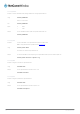
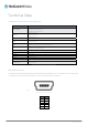
The RJ-45 connect
o
RJ-45 to
D
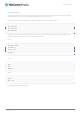
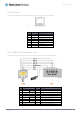
The following table
n
necto
r
o
r provides an interf
a
D
B9 Serial
/
displays the PIN out
DB9
1
2
3
4
5
6
7
8
9
-
a
ce for a serial data
c
Pi
n
PIN
1
2
3
4
5
6
7
8
/
Power Ad
a
configuration for the
SIGNAL
DCD
RXD
TXD
DTR
GND
DSR
RTS
CTS
RI
Power
c
onnection and for d
e
: 8 1
Figur
e
SIGNAL
VCC
DCD
DTR
GND
RXD
TXD
RTS
CTS
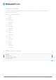
Ta
b
a
pter Cabl
RS-232 serial conn
e
Figure40‐RJ‐4
5
e
vice input power u
s
e
39‐TheRJ‐45Co
n
D
Input voltage 5V
D
Data Carrier Det
e
Data Terminal Re
a
Common Ground
Serial Data out
Serial Data in
Request/Ready t
o
Clear to Send
ble8‐RJ‐45Conne
l
e
e
ction cable that shi
p
5
toDB‐9Serial/Po
w
RJ45
2 Data Car
r
5 Serial Da
t
6 Serial Da
t
3 DTR
4 Common
- Not Use
d
7 Request t
8 Clear to
S
-
Not Use
d
1 Red Wire
:
s
ing the pin layout sh
n
necto
r
D
ESCRIPTION
D
C - 36VDC
ct
a
dy
o
Send
ctorPinOuts
p
s with the NTC-300
0
w
erAdapterCable
DESC
R
r
ier Detect
t
a Out
t
a In
Ground GND (Power Gro
u
d
o Send (received by the N
S
end (transmitted by the N
T
d
:
VCC (Input voltage from
5
o
wn below.
series modems.
R
IPTION
nd)
T
C-3000)
T
C-3000)
5
V – 36VDC)
NT
C
NTC 30
0
C
-3000 Serie
s
0 Series –
M2M
Serial
s
Modem
49