Userr Guide NTC-300 00 Series – M2M M Serial Modem
Copyright mited. All rights reservved. Copyright©2013 NeetComm Wireless Lim The information conntained herein is propprietary to NetComm Wireless Limited. Noo part of this documeent may be translated, transcribed, reprodduced, in any form, or by any means without prior writtenn consent of NetComm m Wireless Limited. Please nnote: This document is subject to change without notice.
NTC-3000 Series 1.3 – Corrected RJ-45 to DB9 Serial/Power Adapter Cable diagram 27/11/2013 Table 1 ‐ Document Revision History www.netcommwireless.
Table of Contents Overview ............................................................................................................................................. 5 Safety and Product Care ........................................................................................................................... 6 Product Introduction ............................................................................................................................... 7 Physical Dimensions and Indicators .....
NTCC-3000 Seriess Overrview Introductioon This document detaails the process of coonfiguring the NTC-30000 Series device viaa a terminal emulation program (such as HyperTerminal) H as weell as mounting and deployment d advice.
Safetty andd Prodduct CCare The NTC-3000 seriees offers a hardened industrial enclosure making it suitable forr a variety of remote deployment locations. ronic device, the folloowing basic guidelinees are recommendedd: With reference to thhe unpacking, installaation, use and mainteenance of your electro IInstallation, configuraation and disassembly should be performmed by trained personnnel only. DDo not use or install this t product near water to avoid fire or sh ock hazard.
NTC-3000 Series Product Introduction Product Overview Small-sized and rugged industrial-grade 3G modem for wireless data communication Provides reliable RS232 serial data connectivity for various M2M applications Supports standard AT command set Supports various networks and service types UMTS/HSDPA/HSUPA & GSM/GPRS/EDGE Embedded Internet and security protocol stacks Wide input voltage range 5-36V DC suitable for diverse environments and applications RS232 serial data connection and power input via RJ45 po
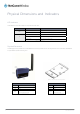
Physical Dimensions and Indicators LED Indicators The NTC-3000 Series uses two LEDs to display the current system and connection status. LED INDICATOR Power 3G COLOUR DEFINITION Off The Power is off. Red The Power is on and the NTC-3000 is operating normally. Off The NTC-3000 is not connected to a 3G network. Slow flashing green The NTC-3000 is attempting to connect to a 3G network. Quick flashing green Data is moving across the 3G connection.
NTCC-3000 Seriess Interffaces The following interfaaces are available onn the NTC-3000 Seriees: INTERFACE FUNCTION RJ-45 (RS-232 DB-9 D adapter / Power) Provides a serial interfaace via a standard Windows modem for AT commandd communication and dial-up networking. The serial modem may also be powered from this innterface using the DB-9 adapter / power cable. c Refer to the Technical Data section of this mannual for more information.
Hardware Installation Inserting the SIM card Please ensure that the NTC-3000 is not connected to the power cable before proceeding. 1. Push the small yellow button besides the SIM card holder. Figure 3 – Accessing the NTC‐3000 SIM Card Slot 2. Insert the SIM card into the holder with the golden SIM conductor pins facing up. Figure 4 ‐ Inserting a SIM Card into the NTC‐3000 SIM Card Holder NTC 3000 Series – M2M Serial Modem 10 www.netcommwireless.
NTC-3000 Series 3. Insert the loaded SIM card holder with the SIM conductor pins facing down into the NTC-3000. Figure 5 –Face Down Insertion of the SIM Card and SIM Card Holder Mounting the device The NTC-3000 series modem can be mounted on the wall or a DIN rail by using the mounting bracket. The mounting bracket is made from polyamide, which is a flexible material. Mounting the NTC-3000 series modem is as simple as bending the mounting bracket to snap into place on the Type-O (Top Hat) DIN rail.
2. Once the bracket is attached to the DIN rail, slide the NTC-3000 Series modem into the mounting bracket to securely fix it in place. Figure 7 ‐ Securing the NTC‐3000 Mounting Bracket to the DIN Rail Wall Mounting 1. Select a position on the wall where you would like to mount the NTC-3000 Series modem. Attach the mounting bracket to the chosen wall or ceiling by using the 4 screw holes (screws not included). 2.
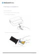
NTCC-3000 Seriess Connectinng the Dataa / Power cables c There are two methods of connecting the NTC-3000 to your computer: VVia RJ-45 connector using a DB9 serial/power adapter cable VVia USB 2.0 port usinng a Mini USB cable Connecting viaa RJ-45 connecttor Figure 8 ‐ Connecting the RRJ‐45 Ethernet / Po ower Cable to the NTC‐3000 1. Connect the optional antenna to the t SMA connector of o the NTC-3000. 2.
NTC 3000 Series – M2M Serial Modem 14 www.netcommwireless.
NTCC-3000 Seriess Connecting viaa Mini USB port The mini USB conneection enables comm munication from a Winndows computer via a virtual COM port. The T NTC-3000 Seriess modem can then bee configured via a terrminal emulator (such as HyperTerm minal). To configure the t internet connectioon settings of the routter, the AirCard Watccher application must be installed on yourr computer.
4. The installation wizard will proceeed to install the softwware and when it has ffinished, the InstallShhield Wizard Completed screen is displayyed. Click Finish to close the wizard. Figure 11 ‐ AIrCard Wattcher InstallShield Wizard W Completed Screen S Verifying succeessful installatioon of the driver To verify the driver wwas successfully insttalled, check in the Device D Manager for eextra COM ports. To check c the Device Manager, perform the foollowing steps: 1. P option.
NTC-3000 Series www.netcommwireless.
Estabblishinng a Mobil M e brooadbaand coonnecction Using the Mini USB port The NTC-3000 Seriees Routers can use the Sierra Wireless AirCard Watcher appli cation to establish ann internet connection. To begin using the NTC-3000 Series Roouter: 1. Connect the NTC-3000 to your coomputer using a mini USB cable. The AirCCard Watcher applicaation should automattically start up and if yyour SIM card is PIN locked, it will prompt you ffor the PIN to unlock it. Enter the PIN and click SEND.
NTC-3000 Series Figure 15 ‐ AIrCard Watcher Options ‐ Add New Profile Screen 5. With the Profiles menu option selected, use the Default Profile drop down list on the right side of the screen to select the profile you created and click OK. Figure 16 ‐ AIrCard Watcher Options ‐ Profiles Options 6. Click Connect to connect to the mobile broadband network. When you are connected, the Connect button changes to a Disconnect button. Figure 17 ‐ AirCard Watcher Application – Connected www.netcommwireless.
Using the RJ-45 connnector The NTC-3000 can be used to dial up too the internet and proovide networking usinng a standard serial modem m driver. Example screenshots are sshown below to demonstrate this process using Winddows XP, however sim milar steps can be ussed in other operatingg systems. 1. Click Start annd then Control Paneel. 2. Double clickk Phone and Modem Options. Figure 18 ‐ Contro rol Panel ‐ Phone an nd Modem Options 3. On the Phone and Modem Optionns window, click Addd 4.
NTCC-3000 Seriess 5. Wait a few m moments until the list isi loaded, then select Standard 33600 bpps modem from the lisst, and click Next. Figure 20 ‐ Add Hardw ware Wizard ‐ Stand dard 33600kbps Modem 6. Select the poort that the NTC-30000 is connected to andd select Next. In the eexample screenshot below, the NTC-30000 is connected via thee serial cable to portt COM1. Figure 21 ‐ Add Hardware Wizzard ‐ COM1 7.
Figure 23 ‐ Phonee and Modem Optio ons ‐ Modems Tab 9. Click on the AAdvanced tab, and tyype the following initialization commands in the Extra initializaation commands field: at+cgdc cont=1,"IP", ,"apn" The ‘apn’ is yyour Access Point Naame e.g. for Telstra you y would type at+ cgdcont=1,"IP","telstr ra.internet"" Click OK. Figure 24 ‐ Standard S 33600kbpss Modem Properties ‐ Extra initializatio on commands 10. Click on Starrt then Control Panel, then double-click on Network Connectioons. 11.
NTC-3000 Series Figure 25 ‐ Network Connections ‐ New Connection 12. The New Connection Wizard is displayed. Click Next > to begin. Figure 26 ‐ New Connection Wizard Welcome Screen 13. Select Connect to the Internet and click Next >. Figure 27 ‐ New Connection Wizard ‐ Connect to the internet 14. Select Setup my connection manually and click Next >. www.netcommwireless.
Figure 28 ‐ New Connection Wizard ‐ Set up my connection manually 15. Select Connect using a dial-up modem and click Next >. Figure 29 ‐ New Connection Wizard ‐ Connect using a dial‐up modem 16. Enter a name for the ISP or connection and click Next >. Figure 30 ‐ New Connection Wizard ‐ Connection Name NTC 3000 Series – M2M Serial Modem 24 www.netcommwireless.
NTC-3000 Series 17. In the Phone Number field, enter *99***1# Click Next >. Figure 31 ‐ New Connection Wizard ‐ Phone Number 18. Select For my use only and click Next >. Figure 32 ‐ New Connection Wizard ‐ My use only 19. If the service from your wireless service provider requires authentication, please enter a username/password into the relevant fields. Your service provider can provide this information if they are required. Click Next >.
20. Click Finish. Figure 34 ‐ New Connection Wizard Complete Screen 21. When you click Finish, the connection window opens prompting you to establish a connection. Click Dial to begin using your NTC-3000 network connection. Figure 35 ‐ Connect to Dial‐up Prompt NTC 3000 Series – M2M Serial Modem 26 www.netcommwireless.
NTC-3000 Series Communicating with an NTC-3000 Series Modem Dumb Terminal Any terminal emulator can be used to facilitate communication with the NTC-3000 after the Virtual COM port has been installed using either the device’s serial port or the USB port. Additionally, you can select to communicate with the modem using your computer’s serial port COM port. The example below demonstrates how to use HyperTerminal in Windows XP. 1.
The terminal window display indicates that a connection is open to the NTC-3000 Series. This can be confirmed by entering the command at and receiving the response OK as shown below: NTC 3000 Series – M2M Serial Modem 28 www.netcommwireless.
NTC-3000 Series Using a terminal emulator such as HyperTerminal and the AT command Reference Guide, the NTC-3000 Series router can be configured to perform customised operations. Please refer to the Supported AT Command Reference Guide available on the NetComm Wireless website at http://www.sierrawireless.com for more information on the functions available. If you are unable to type at, check that you have selected the correct COM port for the NTC-3000.
NetCComm Wireeless OOpen AT Custom C m Applicatioon The NTC-3000 com mes pre-loaded with a NetComm Wireless Open AT custom appplication. This appliccation allows the NTC C-3000 to operate in ddifferent modes, provviding additional functionality and support for a number of o terminal commandss specific to this appplication. These comm mands can be used locally or by SMS to ssend or receive seriaal data to or from GPRS connections.
NTC-3000 Series AT+APN Description: Usage 1: Sets the Access Point Name (APN) used to connect to the broadband network. The default setting is blank. To set the APN AT+APN=xxxx where ‘xxxx’ is the APN that you wish to use. Usage 2: To retrieve the currently configured APN AT+APN? Example: To set the APN to ‘testAPN’ enter AT+APN=testAPN AT+USER_PASS Description: Sets the username and password used to connect to the broadband network.
NTC 3000 Series – M2M Serial Modem 32 www.netcommwireless.
NTC-3000 Series AT+SERIAL_FORMAT Description: Sets the serial format used for communication between the modem and the connected device. Usage 1: To set the serial format AT+SERIAL_FORMAT=x where ‘x’ is an option number.
AT+SERIAL_PARITY Description: Sets the serial parity used for communication between the modem and the connected device. Usage 1: To set the serial parity AT+SERIAL_PARITY=x where ‘x’ is an option number.
NTC-3000 Series AT+SERVER=testhost.domain.com,8888 www.netcommwireless.
AT+Save Description: Saves any changes made to the settings using commands in this list. Changes to settings using the commands in this list do not take effect immediately and must be saved to the board’s flash memory using this command, followed by a reboot. The exception to this is the AT+PAD command which initiates a save command and reboots the device.
NTC-3000 Series AT+SMS_PASSWORD Description: Used to define the password used with the SMS Diagnostics feature. The password is limited to 6 characters. The default password is ‘1234’. Usage 1: To set the SMS password AT+SMS_PASSWORD=XXXXXX Usage 2: To retrieve the current configured password AT+SMS_PASSWORD? Help: AT+SMS_PASSWORD=? Example: To set the password to ‘1234’, enter AT+SMS_PASSWORD=1234 AT+SMS_ACK Description: Sets the status of the SMS acknowledgement feature.
AT+FORCE_RESET Description: Sets the period for which the NTC-3000 will automatically reset. Usage 1: To set the force reset period AT+FORCE_RESET=xxxxx Where ‘x’ is an integer between 2 and 65535 minutes.
NTC-3000 Series AT+CHAR_TIMEOUT=10 www.netcommwireless.
AT+TCP_TIMEOUT Description: This command sets the TCP timeout value in seconds. If the TCP/IP connection is not working, the application will wait for this period of time to re-establish the connection. The minimum timeout period is 10 seconds while the maximum is 65535 seconds. Usage 1: To configure the TCP timeout value AT+TCP_TIMEOUT=xxxxx Where ‘x’ is an integer in seconds between 10 and 65535.
NTC-3000 Series AT+FACTORY_RESET Description: Resets the NTC-3000 to factory default settings, effectively performing the following commands: AT + PAD = 0 AT + APN = AT + USER_PASS = "","" AT + FORCE_RESET = 0 AT + SERVER = ,1516 AT + SMS_DIAGNOSTICS= 0 AT + SMS_ACK = 0 AT + SMS_PASSWORD = 1234 AT + EOL = 0x0D,0x0A AT + SERIAL_BAUD = 115200 AT + SERIAL_FORMAT = 3 AT + SERIAL_PARITY = 4 AT + SERIAL_FLOW = 0 AT + CHAR_TIMEOUT = 8 seconds AT + TCP_TIMEOUT = 10 AT + TCP_RETRY = 0 (In
AT+DYN_ENABLE Description: Instructs the NTC-3000 to enable updating its IP address to the configured Dynamic DNS server. Usage: AT+DYN_ENABLE=x Where ‘x’ is an option number Help: AT+DYN_ENABLE=? Options: 0 1 Example: To set the NTC-3000 to enable star updates to the Dynamic IP address table, enter disable enable AT+DYN_ENABLE=1 AT+DYN_HOST Description: Instructs the NTC-3000 to use the supplied hostname to perform an IP address update.
NTC-3000 Series General Operation Upon powering up, the application subscribes to the SMS service and sets up customized AT commands. It then reads the configuration from FLASH. If the device is configured in normal modem mode (AT+PAD=0), the application will not start GSM or GPRS initialization, TCP or UDP preparation routines. When TCP/IP has been set up, an IP address will be issued to the NTC-3000.
Configuration through SMS The NTC-3000 can be configured through the serial port with AT commands or remotely through SMS messages. When configuring the NTC-3000 using SMS messages, all the messages must be prefixed with a password. The following is a list of SMS commands that may be used: 1. get status 2. get settings 3. get version 4. get force_reset 5. get serial_on_start 6. execute reboot 7. execute save 8. execute pdpcycle 9. execute pdpdown 10. execute pdpup 11. set apn 12.
NTC-3000 Series get settings The NTC-3000 replies with the following information: APN: testAPN PDP: testuser@domain.com.au, test SERVER: 10.1.193.11,1516 PAD: 1 DYN_ENABLE: 1 DYN_HOST: testuser.dyndns.org DYN_USER: testuser DYN_PASS: testpass get version The NTC-3000 replies with the version of the NetComm Wireless custom application. get force_reset The NTC-3000 replies with the current FORCE_RESET period. get serial_on_start The NTC-3000 replies with the current SERIAL_ON_START flag.
NTC 3000 Series – M2M Serial Modem 46 www.netcommwireless.
NTC-3000 Series set server= ip address/hostname, port Sets the server IP address or hostname and port that the NTC-3000 will use when operating in TCP server mode. set dyn_enable=0,1 When this value is set to 1, the NTC-3000 automatically updates the IP address from the dynamic DNS host. When this value is set to 0, the dynamic DNS feature is disabled. set dyn_host=xxx Sets the Dynamic DNS hostname. set dyn_user=xxx Sets the Dynamic DNS username. set dyn_pass=xxx Sets the Dynamic DNS password.
Technical Data The following table lists the hardware specifications of the NTC-3000 Series devices. MODEL NETCOMM NTC-3000 SERIES Sierra Wireless AirPrime SL8080T (NTC-3000-01) Modem Chipset/Module Sierra Wireless AirPrime SL8082T (NTC-3000-02) Sierra Wireless AirPrime SL8084T (NTC-3000-03) UMTS 850/1900 (NTC-3000-01) UMTS bands UMTS 900/2100 (NTC-3000-02) GSM bands Quad-band EDGE/GPRS/GSM 850/900/1800/1900MHz Maximum Data Throughput / 3G Radio interface Peak download rate: 3.
NTCC-3000 Seriess RJ-45 Connnector The RJ-45 connectoor provides an interfaace for a serial data connection c and for deevice input power ussing the pin layout shown below.
Table 9 ‐ RJ‐45 to DB‐9 Serial/Power Connector Pin Outs The NTC-3000 is a DCE (Data Circuit-Terminating Environment), so the RTS (Ready To Send) signal is received by the NTC-3000 and the CTS (Clear to Send) signal is transmitted with flow controlled from both ends. The DCD (Data Carrier Detect) line is permanently set to one state, i.e. in the high state at the connector, GND at the chip.
NTCC-3000 Seriess Product Servicee andd Suppport The following sectioon provides some asssistance with issues that t may be encounttered when using the NTC-3000 series as well as providing weeb based links for prooduct specific information. Troubleshhooting 1) I am uunable to send any AT A commands to the NTC-3000 N VVerify the NTC-3000 is connected to bothh the power supply annd an appropriate CO OM port. VVerify the LEDs on thhe front of the NTC-30000 are illuminated.
Web Baseed Productt Referencees The following refereence information is also available for the NTC-3000 N Series fromm the NetComm Suppport website at http://www.netcomm mwireless.com/produuct/m2m/ntc-3000 UUser Manual QQuick Start Guide PProduct Specificationn Sheet FAQs Q: A: Is the NTC-3000 series a 3G 3 serial modem? The NNTC-3000 series is abble to operate as a 3G G serial modem, howwever it is also so mucch more.
NTC-3000 Series Appendix A: Tables Table 1 - Document Revision History..................................................................................................................................................................................... 3 Table 2 - LED Indicators ........................................................................................................................................................................................................ 8 Table 3 - Device Dimensions .
Safety and product care RF Exposure Your device contains a transmitter and a receiver. When it is on, it receives and transmits RF energy. When you communicate with your device, the system handling your connection controls the power level at which your device transmits. This device meets the government’s requirements for exposure to radio waves.
NTC-3000 Series IC regulations This device complies with Industry Canada licence-exempt RSS standard(s). Operation is subject to the following two conditions: (1) this device may not cause interference, and (2) this device must accept any interference, including interference that may cause undesired operation of the device. Le présent appareil est conforme aux CNR d’Industrie Canada applicables aux appareils radio exempts de licence.
Product handling You alone are responsible for how you use your device and any consequences of its use. You must always switch off your device wherever the use of a mobile phone is prohibited. Do not use the device without the clip-on covers attached, and do not remove or change the covers while using the device. Use of your device is subject to safety measures designed to protect users and their environment. Always treat your device and its accessories with care and keep it in a clean and dust-free place.
NTC-3000 Series Hearing aids People with hearing aids or other cochlear implants may experience interfering noises when using wireless devices or when one is nearby. The level of interference will depend on the type of hearing device and the distance from the interference source, increasing the separation between them may reduce the interference. You may also consult your hearing aid manufacturer to discuss alternatives.
Legal and Regulatory Intellectual Property Rights All intellectual property rights (including copyright and trade mark rights) subsisting in, relating to or arising out this Manual are owned by and vested in NetComm Wireless Limited (ACN 002490486) (NetComm Wireless Limited) (or its licensors). This Manual does not transfer any right, title or interest in NetComm Wireless Limited’s (or its licensors’) intellectual property rights to you.
NTC-3000 Series Product Warranty All NetComm Wireless products have a standard two (2) year warranty from date of purchase (Product Warranty). For all Product Warranty claims you will require proof of purchase. All Product Warranties are in addition to your rights and remedies under applicable Consumer Protection Laws which cannot be excluded (see Section 3 above).
Phone: +61(0)2 9424 2070 Fax: +61(0)2 9424 2010 Email: sales@netcommwireless.com, technicalsupport@netcommwireless.com NTC 3000 Series – M2M Serial Modem 60 www.netcommwireless.