
User's Manual


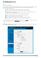
Table Of Contents
- Introduction
- Target audience
- Prerequisites
- Notation
- Product overview
- Product features
- Package contents
- Physical dimensions
- LED indicators
- Ethernet port LED indicators
- Interfaces
- Mounting options
- DIN rail mounting bracket
- Wall mounted via DIN rail bracket
- DIN rail mount
- Pole mount using DIN rail bracket
- Desk mount
- Powering the router
- Installing the router
- Data Connection
- Connect on demand
- SIM Management
- Operator settings
- SIM security settings
- LAN
- Wireless settings
- Ethernet LAN/WAN
- WAN failover
- Routing
- VPN
- Dynamic DNS
- Network time (NTP)
- Data stream manager
- PADD
- SNMP
- TR-069
- GPS
- USSD
- IO configuration
- SMS messaging
- Diagnostics
- Sending an SMS Diagnostic Command
- Log
- System configuration
- Administration
- Watchdogs
- Power management
- USB-OTG
- Storage
- Reboot
- Restoring factory default settings
- Accessing recovery mode
- Status
- Log
- Application Installer
- Settings
- Reboot
- Overview
- Accessing USB/SD card storage devices
- Host and Device mode

88
NetComm Wireless 4G WiFi M2M Router
www.netcommwireless.com
UM-00009
IO configuration
The NTC-140W Series Router is equipped with a 2 x 2 Molex connector providing Power (+), Ground (−), a multipurpose input and
output pin and an ignition detection input. The multipurpose input/output pin may be independently configured for various functions,
including:
NAMUR (EN 60947-5-6 / IEC 60947-5-6) compatible proximity sensor input
Proximity sensor input for use with contact closure (open/closed) type of sensors (PIR sensors, door/window sensors
for security applications) with the input tamper detection possible (four states detected: open, closed, short and break)
by the use of external resistors
Analogue 0V to 30V input
Digital input (the I/O voltage measured by the Analogue input and the software making decision about the input state)
with the threshold levels configurable in software
Open collector output.
Use the pull up voltage options to select the desired output voltage of the I/O pins. The pull up voltage you select will be the same
for each pin when pull up is enabled for that pin. Each pin is capable of outputting either 3.3V or 8.2V.
Figure 105 – IO configuration options
ITEM
DESCRIPTION
IO configuration
IO Functionality
Enables the configuration of the input and output pins on the 2x2 Molex connector.
Pull up voltage
Specifies the output voltage of the I/O pins.
IO Manager Debug level
Use the slide bar to adjust the level of detail you would like to see in the log for IO messages. A
higher debug level displays more detailed messages in the log file.
Per pin configuration
Pin
The I/O pin number corresponding to the pin on the Molex connector that you wish to configure.
Mode
The mode of operation for the corresponding pin. Available options are Digital input, Digital output,
Analogue input, Namur input, Contact closure input.
Pull up
Use the pull up toggle keys to turn the pull up on or off for the corresponding pin. When turned on,
the pull up voltage output is the value specified in the “Pull up voltage” option.
Value
The value column displays whether the voltage detected on the line is low or high or allows you to
configure the output value in the case that the pin is set to digital output. This can be useful for
applications where monitoring of the transition between low and high is used to trigger an action.
Table 26 - IO configuration options