
User's Manual
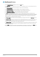
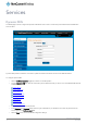

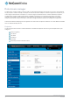


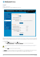
Table Of Contents
- Introduction
- Target audience
- Prerequisites
- Notation
- Product overview
- Product features
- Package contents
- Physical dimensions
- LED indicators
- Ethernet port LED indicators
- Interfaces
- Mounting options
- DIN rail mounting bracket
- Wall mounted via DIN rail bracket
- DIN rail mount
- Pole mount using DIN rail bracket
- Desk mount
- Powering the router
- Installing the router
- Data Connection
- Connect on demand
- SIM Management
- Operator settings
- SIM security settings
- LAN
- Wireless settings
- Ethernet LAN/WAN
- WAN failover
- Routing
- VPN
- Dynamic DNS
- Network time (NTP)
- Data stream manager
- PADD
- SNMP
- TR-069
- GPS
- USSD
- IO configuration
- SMS messaging
- Diagnostics
- Sending an SMS Diagnostic Command
- Log
- System configuration
- Administration
- Watchdogs
- Power management
- USB-OTG
- Storage
- Reboot
- Restoring factory default settings
- Accessing recovery mode
- Status
- Log
- Application Installer
- Settings
- Reboot
- Overview
- Accessing USB/SD card storage devices
- Host and Device mode

www.netcommwireless.com
NetComm Wireless 4G WiFi M2M Router
77
UM-00009
GPS data: This creates a GPS data endpoint.
Figure 92 - GPS data endpoint configuration
4.
Click the OK button. The router displays a screen with configuration options for your chosen endpoint type.
5.
Enter the options for your endpoint as required.
6.
Click the Save button. The Endpoints list is displayed with the newly created endpoint listed and a summary of the settings
your configured.
Figure 93 - Endpoints list
Streams
When you have created the required endpoints, you can then proceed to set up a data stream. A data stream sends data from one
endpoint to another, performing any transformation of the data as required. When a stream is added, an underlying process on the
router checks the validity of the stream, checking for conflicts and illogical configurations.
Every stream requires two endpoints, Endpoint A and Endpoint B. In all cases, the flow of data is from Endpoint A to Endpoint B.
To create a new stream:
7.
Click the +Add button on the right side of the page.
Figure 94 - Data stream list
The Edit data stream page is displayed.
8.
In the Data stream name field, enter a name for the Data stream.
9.
Under Endpoint A, use the Endpoint name drop down list to select one of the endpoints you created previously. This
endpoint should be the starting point of the stream. Use the Mode drop down list to select the mode of operation of the
endpoint. The mode can be thought of as a transformation of the data as it leaves this endpoint. For example, if Endpoint
A type is Serial port (generic), the Mode can be set to various Modbus server and client types. This means that upon arrival
at Endpoint A, the data will be transformed into the chosen Modbus format, ready to be sent to Endpoint B.
Notes on data stream operation:
When any changes to the Data stream manager configuration are detected, all data streams are stopped and
restarted as per the new configuration.
Multiple Modbus clients cannot connect simultaneously to Modbus serial slaves connected to the router.