
User's Manual
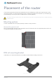
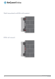

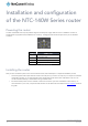
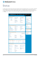


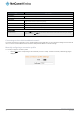
Table Of Contents
- Introduction
- Target audience
- Prerequisites
- Notation
- Product overview
- Product features
- Package contents
- Physical dimensions
- LED indicators
- Ethernet port LED indicators
- Interfaces
- Mounting options
- DIN rail mounting bracket
- Wall mounted via DIN rail bracket
- DIN rail mount
- Pole mount using DIN rail bracket
- Desk mount
- Powering the router
- Installing the router
- Data Connection
- Connect on demand
- SIM Management
- Operator settings
- SIM security settings
- LAN
- Wireless settings
- Ethernet LAN/WAN
- WAN failover
- Routing
- VPN
- Dynamic DNS
- Network time (NTP)
- Data stream manager
- PADD
- SNMP
- TR-069
- GPS
- USSD
- IO configuration
- SMS messaging
- Diagnostics
- Sending an SMS Diagnostic Command
- Log
- System configuration
- Administration
- Watchdogs
- Power management
- USB-OTG
- Storage
- Reboot
- Restoring factory default settings
- Accessing recovery mode
- Status
- Log
- Application Installer
- Settings
- Reboot
- Overview
- Accessing USB/SD card storage devices
- Host and Device mode

14
NetComm Wireless 4G WiFi M2M Router
www.netcommwireless.com
UM-00009
Installation and configuration
of the NTC-140W Series router
Powering the router
The NTC-140W Series router may be powered using the included power supply cable with 8-40V to the Molex connector. A
suitable power supply (PSU-0039) is available as an accessory. The diagram below shows the layout of the pins on the Molex
connector.
Figure 11 - Molex connector
TERMINAL
DESCRIPTION
−
Ground wire.
+
Positive wire for power.
i
Dedicated terminal for ignition detection.
I/O
Input/output detection.
Table 7 - Locking power block pin outs
Installing the router
After you have connected a power source and mounted the router, follow these steps to complete the installation process.
1.
Connect equipment that requires network access to the LAN port of your router. This may be your computer for advanced
configuration purposes, or your end equipment which requires data access via the NTC-140W Series router. You can
connect one device directly, or several devices using a network switch.
2.
Ensure the external power source is switched on and wait 2 minutes for your NTC-140W Series router to start up. To
check the status of your router, compare the LED indicators on the device with those listed in the LED indicators section of
this guide.