
User's Manual

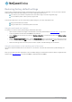


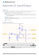
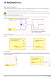
Table Of Contents
- Introduction
- Target audience
- Prerequisites
- Notation
- Product overview
- Product features
- Package contents
- Physical dimensions
- LED indicators
- Ethernet port LED indicators
- Interfaces
- Mounting options
- DIN rail mounting bracket
- Wall mounted via DIN rail bracket
- DIN rail mount
- Pole mount using DIN rail bracket
- Desk mount
- Powering the router
- Installing the router
- Data Connection
- Connect on demand
- SIM Management
- Operator settings
- SIM security settings
- LAN
- Wireless settings
- Ethernet LAN/WAN
- WAN failover
- Routing
- VPN
- Dynamic DNS
- Network time (NTP)
- Data stream manager
- PADD
- SNMP
- TR-069
- GPS
- USSD
- IO configuration
- SMS messaging
- Diagnostics
- Sending an SMS Diagnostic Command
- Log
- System configuration
- Administration
- Watchdogs
- Power management
- USB-OTG
- Storage
- Reboot
- Restoring factory default settings
- Accessing recovery mode
- Status
- Log
- Application Installer
- Settings
- Reboot
- Overview
- Accessing USB/SD card storage devices
- Host and Device mode

www.netcommwireless.com
NetComm Wireless 4G WiFi M2M Router
139
UM-00009
Appendix G: Input/Output
Overview
The NTC-140W series router is equipped with a 2 x 2 Molex connector providing a multipurpose input and output terminal as well
as a dedicated ignition input. The I/O terminal may be independently configured for various functions, including:
NAMUR (EN 60947-5-6 / IEC 60947-5-6) compatible sensor input
Proximity sensor input for use with contact closure (open/closed) type of sensors (PIR sensors, door/window sensors
for security applications) with the input tamper detection possible (four states detected: open, closed, short and break)
by the use of external resistors
Analogue 0V to 30V input
Digital input (the I/O voltage measured by the Analogue input and the software making a decision about the input state)
with the threshold levels configurable in software
Open collector output.
Hardware Interface
The interface of the input/output terminals are based on the circuit diagram below
The Input/Output label is the physical connection to the outside world. There are protection devices and resistor dividers to
condition the signal prior to it going into the processor. The three labels to the right are the interface to the processor. Output
Enable activates the Transistor which provides an open collector (ground) output and can sink 200mA at 23
0
C. It is protected by a
resettable fuse and transient protection diode. If used with the pull up resistor, which can be activated by the Pull up Voltage Enable
pin, then you can have a High or Low output rather than open drain. The resistor can be pulled up to 3V3 for Cmos compatible
output or 8.2V by software. The Analogue Input pin can read values from 0V to 30V. It is divided by a resistor network to read
appropriate levels in the processor. Depending on the sensor type used, the pull up resistor can be switched on or off. If using the
NAMUR sensor configuration the pull up will be activated to 8V2 by default.