
User's Manual


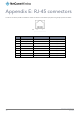
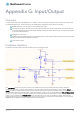
Table Of Contents
- Introduction
- Target audience
- Prerequisites
- Notation
- Product overview
- Product features
- Package contents
- Physical dimensions
- LED indicators
- Ethernet port LED indicators
- Interfaces
- Mounting options
- DIN rail mounting bracket
- Wall mounted via DIN rail bracket
- DIN rail mount
- Pole mount using DIN rail bracket
- Desk mount
- Powering the router
- Installing the router
- Data Connection
- Connect on demand
- SIM Management
- Operator settings
- SIM security settings
- LAN
- Wireless settings
- Ethernet LAN/WAN
- WAN failover
- Routing
- VPN
- Dynamic DNS
- Network time (NTP)
- Data stream manager
- PADD
- SNMP
- TR-069
- GPS
- USSD
- IO configuration
- SMS messaging
- Diagnostics
- Sending an SMS Diagnostic Command
- Log
- System configuration
- Administration
- Watchdogs
- Power management
- USB-OTG
- Storage
- Reboot
- Restoring factory default settings
- Accessing recovery mode
- Status
- Log
- Application Installer
- Settings
- Reboot
- Overview
- Accessing USB/SD card storage devices
- Host and Device mode

138
NetComm Wireless 4G WiFi M2M Router
www.netcommwireless.com
UM-00009
Appendix E: RJ-45 connectors
The RJ-45 connectors provide an interface for a data connection and for device input power using the pin layout shown below.
Pin: 8 1
Figure 151 -The RJ-45 connector
PIN
COLOUR
SIGNAL (10/100)
SIGNAL (1000)
1
White/Orange stripe
Rx + DC +
+BI_DA
2
Orange Solid
Rx - DC +
-BI_DA
3
White/Green stripe
Tx + DC -
+BI_DB
4
Blue solid
unused
+BI_DC
5
White/Blue stripe
unused
-BI_DC
6
Green solid
Tx - DC -
-BI_DB
7
White/Brown stripe
unused
+BI_DD
8
Brown solid
unused
-BI_DD
Table 43 - RJ-45 connector pin outs