
User's Manual
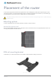
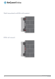

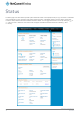


Table Of Contents
- Introduction
- Target audience
- Prerequisites
- Notation
- Product overview
- Product features
- Package contents
- Physical dimensions
- LED indicators
- Ethernet port LED indicators
- Interfaces
- Mounting options
- DIN rail mounting bracket
- Wall mounted via DIN rail bracket
- DIN rail mount
- Pole mount using DIN rail bracket
- Desk mount
- Powering the router
- Installing the router
- Data Connection
- Connect on demand
- SIM Management
- Operator settings
- SIM security settings
- LAN
- Wireless settings
- Ethernet LAN/WAN
- WAN failover
- Routing
- VPN
- Dynamic DNS
- Network time (NTP)
- Data stream manager
- PADD
- SNMP
- TR-069
- GPS
- USSD
- IO configuration
- SMS messaging
- Diagnostics
- Sending an SMS Diagnostic Command
- Log
- System configuration
- Administration
- Watchdogs
- Power management
- USB-OTG
- Storage
- Reboot
- Restoring factory default settings
- Accessing recovery mode
- Status
- Log
- Application Installer
- Settings
- Reboot
- Overview
- Accessing USB/SD card storage devices
- Host and Device mode

www.netcommwireless.com
NetComm Wireless 4G WiFi M2M Router
11
UM-00009
Placement of the router
The four external high-performance antennas supplied with the router are designed to provide optimum signal strength in a wide
range of environments. If you find the signal strength is weak, try adjusting the orientation of the antennas. If you are unable to get
an acceptable signal, try moving the router to a different place or mounting it differently.
Note: When selecting a location for the router, allow at least 20 seconds for the signal strength LEDs to update before trying
a different location.
Mounting options
The NTC-140W Series router can be quickly and easily mounted in a variety of locations.
Mounted flat against the wall
When mounted flat against the wall, the NTC-140W Series router has a slimline form factor. Use appropriately sized screws in the
mounting holes provided on the base of the unit.
Figure 5 - Wall mount - Flat against the wall
DIN rail mounting bracket
V Bend allows you to snap the DIN bracket onto the middle of a DIN rail rather than sliding it onto the end.
Figure 6 – DIN rail mounting bracket