
User's Manual


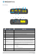
Table Of Contents
- Introduction
- Target audience
- Prerequisites
- Notation
- Product overview
- Product features
- Package contents
- Physical dimensions
- LED indicators
- Ethernet port LED indicators
- Interfaces
- Mounting options
- DIN rail mounting bracket
- Wall mounted via DIN rail bracket
- DIN rail mount
- Pole mount using DIN rail bracket
- Desk mount
- Powering the router
- Installing the router
- Data Connection
- Connect on demand
- SIM Management
- Operator settings
- SIM security settings
- LAN
- Wireless settings
- Ethernet LAN/WAN
- WAN failover
- Routing
- VPN
- Dynamic DNS
- Network time (NTP)
- Data stream manager
- PADD
- SNMP
- TR-069
- GPS
- USSD
- IO configuration
- SMS messaging
- Diagnostics
- Sending an SMS Diagnostic Command
- Log
- System configuration
- Administration
- Watchdogs
- Power management
- USB-OTG
- Storage
- Reboot
- Restoring factory default settings
- Accessing recovery mode
- Status
- Log
- Application Installer
- Settings
- Reboot
- Overview
- Accessing USB/SD card storage devices
- Host and Device mode

10
NetComm Wireless 4G WiFi M2M Router
www.netcommwireless.com
UM-00009
Interfaces
Figure 4 - Interfaces
NO.
ITEM
DESCRIPTION
1
Cellular Main antenna connector
SMA connector for main cellular antenna.
2
GPS antenna connector
SMA connector for GPS antenna (not included in package).
3
Cellular AUX antenna connector
SMA connector for auxiliary cellular antenna.
4
WiFi antenna connectors
Reverse polarity SMA connectors for WiFi antennas.
5
MicroSD card slot
Insert a MicroSD card here to provide additional storage (Optional).
6
SIM card slot
Insert SIM card here.
7
SIM tray eject button
Press to eject the SIM tray
8
Mini USB 2.0 OTG port
Provides connectivity for optional external storage or a USB Ethernet dongle. Supplies up to 0.5A to
connected device.
9
Reset button
Press and hold for less than 5 seconds to reboot to normal mode. The LEDs are green and extinguish in
sequence to indicate that the router will reboot normally if the button is released during this period.
Press and hold for 5 to 15 seconds to reboot to recovery mode. The LEDs are amber and extinguish in
sequence to indicate that the router will reboot to recovery mode if the button is released during this
period.
Press and hold for 15 to 20 seconds to reset the router to factory default settings. The LEDs are red and
extinguish in sequence to indicate that the router will reset to factory default settings if the button is
released during this period.
10
Molex Mini-Fit™ Jr. 2 x 2 receptacle
Connect the provided power supply here. The Molex receptacle provides:
Ground (−)
Power (+)
I/O terminal
(i) ignition input detection terminal.
11
LAN port
LAN port for wired Ethernet clients.
12
LAN/WAN port
LAN or WAN port for wired Ethernet clients or to bridge another network connection.
Table 6 – Interfaces
8
9
10
1
11
12
4
2
5
6
7
1
3