casa systems User Guide CFW-2182 CBRS 4G Outdoor UE Doc No.
of 63 Important notice This device, like any wireless device, operates using radio signals which cannot guarantee the transmission and reception of data in all conditions. While the delay or loss of signal is rare, you should not rely solely on any wireless device for emergency communications or otherwise use the device in situations where the interruption of data connectivity could lead to death, personal injury, property damage, data loss, or other loss.
of 63 Contents Overview ..................................................................................................................................... 6 Introduction....................................................................................................................................................................................................... 6 Target audience .......................................................................................................................
of 63 Operator settings ...........................................................................................................................................................................................................................35 SIM security settings ................................................................................................................................................................................ 36 Unlocking a PIN locked SIM .................................
of 63 Appendix A – Default Settings ......................................................................................................... 61 Appendix B – Safety and compliance ................................................................................................. 62 RF Exposure ..................................................................................................................................................................................................... 62 FCC Statement..
of 63 Overview Introduction This document provides all the information required to configure and deploy the Casa Systems CFW-2182 antenna. This User Guide relates to the CFW-2182’s physical components and its web user interface. Normally only the installing technician would require access to the CFW-2182’s web user interface, if at all. End users would not normally ever need to access this web user interface and would probably be unaware of it.
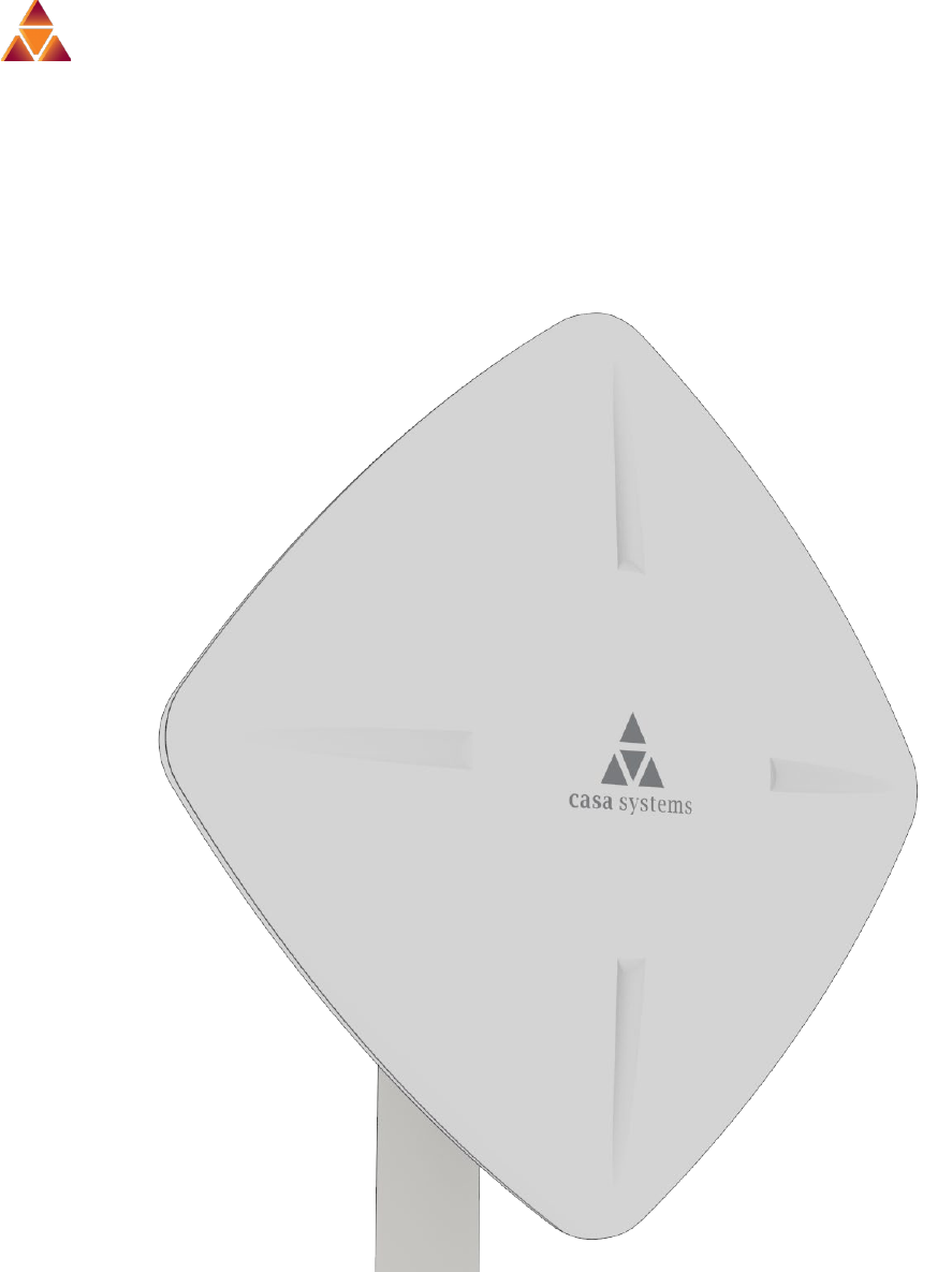
of 63 Product introduction Product overview Rural and regional homes and businesses, remote commercial sites and metropolitan fringe districts located beyond the reach of fixed line infrastructure rely on mobile networks to access broadband Internet.
of 63 Physical dimensions and interfaces Physical dimensions Below is a list of the physical dimensions of the CFW-2182. Figure 1 – CFW-2182 Dimensions CFW-2182 Dimensions Length 15 ½” (395 mm) Width 15 ½” (395 mm) Height 4 ½” (75 mm) Weight ~5.7lbs (~2.6 kg) Table 1 - Device Dimensions CFW-2182 – User Guide UG01233 v1.
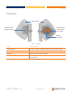
of 63 Interfaces Antenna panel Smart Antenna Tool port with tool in place Antenna Power Supply port (PoE) SIM card access hatch Figure 2 – Interfaces Item Description Antenna panel Includes 2 x pairs Cross polarised antennas and GPS antenna Smart Antenna Tool port Connect the Smart Antenna Tool here SIM hatch Open the hatch to insert SIM here Antenna Power Supply port (PoE) Provides power and data connectivity to the CFW-2182 with Ethernet cable Table 2 – Interfaces CFW-2182 – User Guide U
of 63 Insert SIM card The CFW-2182 accepts SIM cards in Mini-SIM (3FF) format. Follow the instructions below to insert a SIM card. 1 On the back of the CFW-2182 antenna, locate the SIM hatch. Using a T10 screwdriver, unscrew the two screws on the SIM hatch then remove the cover to reveal the SIM card slot. Figure 3 - Removing screws from the SIM hatch 2 Swing the SIM card locking mechanism down to allow insertion of the SIM card.
of 63 3 Place the SIM card onto the SIM card reader as shown in the picture below. Figure 5 – Placing the SIM card onto the SIM card reader 4 While holding the SIM card onto the reader, swing the locking mechanism up and ensure that it clips into place to secure the SIM card. . Figure 6 - SIM card locked in place CFW-2182 – User Guide UG01233 v1.
of 63 5 Replace the SIM hatch and seal, insert the two screws and firmly hand tighten them using a T10 screwdriver. Figure 7 - Replacing the SIM hatch CFW-2182 – User Guide UG01233 v1.
of 63 Assemble and attach the mounting bracket Overview of completed mounting Antenna housing Mast Left bracket bolt Bracket plate Elevation setting bolt Right bracket bolt Figure 8 - CFW-2182 mounting bracket and bolts Notes on mounting: Use a standard 13m socket wrench for all bolts Tighten bolts to the following torque settings: Captive radome mount bolts: 4 Nm / 35 in-lbs Angle pivot bolt: 7 Nm / 65 in-lbs Pipe clamp bolt: 7 Nm / 65 in-lbs Do not over tighten bolts CFW-2
of 63 Mounting bracket assembly instructions 1 Place the pipe bracket onto the radome mount bracket as shown below. Adjustable elevation control Fixed elevation control Figure 9 – Elevation control components 2 Insert the pivot bolt into the pipe clamp, then place the washer and nut over the pivot bolt as shown below. Elevation setting bolt Elevation setting bolt nut and washer Figure 10 - Attaching the mounting bracket to the CFW-2182 CBRS 4G Outdoor UE CFW-2182 – User Guide UG01233 v1.
of 63 3 Tighten the lock nut so that the pipe bracket and radome mount do not swivel easily. Do not overtighten the pivot bolt as some adjustment may be required later. Figure 11 - Assembling pipe bracket to pole 4 Alternately tighten the top and bottom pipe clamp bolts to maintain even pressure on the pipe, to 80 in-lb. Figure 12 - Tightening pipe clamp bolts CFW-2182 – User Guide UG01233 v1.
of 63 Power the CFW Power over Ethernet (PoE) is a method of connecting network devices through Ethernet cable where power and data are passed along a single cable. It is therefore a convenient method of powering the CFW. Note – The CFW Power supply is packaged and supplied separately. R45 cable weather seal assembly The CFW-2182 antenna’s power supply weather seal must be properly attached to prevent dust and water from entering the CFW-2182’s housing.
of 63 4 Place the Ethernet cable through the nut first, as shown below. Figure 15 - Nut placed over Ethernet cable 5 Place the ferrule over the Ethernet cable as shown, making sure that the “teeth” are facing the nut. Figure 16 - Ferrule placed over Ethernet cable 6 Place the rubber seal over the Ethernet cable with the wide end toward the RJ45 plug. See the image below for the correct orientation. Figure 17 - Rubber seal placed over Ethernet cable CFW-2182 – User Guide UG01233 v1.
of 63 7 Push the ferrule over the rubber seal to prevent it from coming apart. Figure 18 - Ferrule placed over rubber seal 8 Place the washer seal over the Ethernet cable as shown below. Ensure that the inside protruding lip is on the opposite side of the Ethernet plug. Figure 19 - Washer seal placed over Ethernet cable 9 Place the neck over the Ethernet cable as shown below. Figure 20 - Neck placed over Ethernet cable CFW-2182 – User Guide UG01233 v1.
of 63 10 Plug the Ethernet cable into the Ethernet port. Figure 21 - Plugging in the Ethernet cable 11 Put the neck into the opening and turn the neck clockwise until it locks in place. 12 Push the rubber seal and ferrule into the neck then screw the nut on to the neck. Figure 22 - Rubber seal and ferrule inserted into neck 13 Turn the nut clockwise to tighten it the washer seal against the housing. Continue turning the nut until completely assembled.
of 63 PoE-03 power supply Use the PoE-03 power supply to power your CFW-2182: 1 Connect the Antenna Power Supply (POE-03) to a dedicated AC power outlet away from running water, steam and excessive heat. a Switch the outlet ON if required. 2 Plug the end of the R45 Ethernet cable that does not have the weather-sealed plug into the R45 socket named WALL on the PoE-03.
of 63 Installation The positioning and installation of the CFW-2182 antenna is achieved by a trained technician using the Casa Systems Smart Antenna Tool. Details about the Smart Antenna Tool and the complete CFW-2182 installation process are fully described in the CFW-2182 Installation Guide (doc no IG1225). Typical CFW antenna installation The image below illustrates a typical installation of the CFW-2182 CBRS 4G Outdoor UE on the side of a building.
of 63 CFW-2182 configuration interface Normal configuration In most cases the default settings should work as soon as the ethernet power supply is connected to AC power and the PoE port is connected to the CFW-2182. Advanced configuration For advanced configuration, log in to the web-based user interface of the CFW-2182. A full suite of settings is available to customise the configuration of your wireless network connection. Log in To log in to the web-based user interface: 1 Open a web browser (e.g.
of 63 Confirm successful connection To confirm the connection status, click the Status menu item at the top of the page to display the Status page. When there is a mobile broadband connection, the WWAN connection status section is expanded showing the details of the connection and the Status field displays Connected. To see details on the connected session, you can click the Show data usage button. Figure 26 - WWAN connection status section CFW-2182 – User Guide UG01233 v1.
of 63 Status The Status page of the web interface provides system related information and is displayed when you initially log in to the CFW-2182 management console. Figure 27 – Status page CFW-2182 – User Guide UG01233 v1.
of 63 The Status page shows System information, LAN details, Cellular connection status, WWAN connection status, Advanced status and Cell information details. You can toggle the sections from view by clicking the information displayed for each. or buttons to expand or collapse the amount of The following table contains a description of each of the items on the Status page. Item Definition System information System up time The current uptime of the CFW.
of 63 Item Definition WWAN connection status Profile name The name of the currently active profile. Status The connection status of the currently active profile. Default profile Indicates whether the current profile in use is the default profile. WWAN IP The IP address assigned by the mobile broadband carrier network. DNS server The primary and secondary DNS servers for the WWAN connection. APN The Access Point Name currently in use.
of 63 Item Definition RSRP The Reference Signal Received Power value is a cell-specific reference signal used to determine RSRP. RSRQ The Reference Signal Received Quality value calculates signal quality taking into consideration the RSSI. It is calculated by N x RSRP / RSSI where N is the number of Physical Resources Blocks (PRBs) over which the RSSI is measured. Serving A green check mark indicates that the cell location is currently functioning.
of 63 Configuration tool menus Advanced configuration settings are arranged into three menu groups accessible by clicking the buttons which appear to the left of the Status button in the top tool bar: Networking, Services and System. Click on one of the menu buttons and its corresponding menu will appear in the left margin. Many of the menu items have submenus. Click the v down arrow to expand the submenus.
of 63 Networking The Networking tool group provides configuration options for Wireless WAN and LAN connections. The Wireless WAN section contains three groups useful in managing your network connection and SIM card security. Settings in the LAN section allow you to configure a new IP Address and/or Subnet mask for the antenna and to enable or disable DNS Masquerading. CFW-2182 – User Guide UG01233 v1.
of 63 Wireless WAN Data connection The data connection page allows you to configure and enable/disable connection profiles. To access this page, click on the Networking menu, and under the Wireless WAN menu, select the Data connection item. The profile refers to a set of configuration items which are used by the antenna to activate a Packet Data (PDP) context. The is only one profile defined for the CFW-2182.
of 63 Status Toggles the corresponding profile ON or OFF. Only one profile may be turned on at any time. APN The Access Point Name assigned to the corresponding profile. Username The username used to log on to the corresponding APN. Save button Click the Save button to save and apply any changes.
of 63 3 Once enabled, additional profile details will display: Figure 30 - Data connection settings - Profile turned on 4 The Profile name is a system defined name used to reference the profile. 5 In the APN field, enter the APN Name (Access Point Name) and if required, use the Username and Password fields to enter your login credentials (if required). 6 Next to Authentication type, select the either CHAP, PAP or None depending on the type of authentication used by your provider.
of 63 and received to inform remote computers on the internet that packets originating from a machine behind the antenna actually originated from the WAN IP address of the antenna’s internal NAT IP address. This may be disabled if a framed route configuration is required and local devices require WAN IP addresses. 11 Click the Save button when you have finished entering the profile details.
of 63 Figure 32 - Data usage Click the Show duration link to toggle the display to show the duration of each session rather than the start and end times. Figure 33 - Data usage with connection duration CFW-2182 – User Guide UG01233 v1.
of 63 Operator settings The Operator settings page enables you to select which frequency band you will use for your connection and enables you to scan for available network operators in your area. You may want to do this if you’re using the antenna in a country with multiple frequency networks that may not all support LTE. You can select the antenna to only connect on the network frequencies that suit your requirements.
of 63 A list of the detected service carriers in your area is displayed. Figure 35 - Detected operator list Select the most appropriate service from the list shown and click the Apply button. When Select operator mode is set to Automatic, the antenna selects the most appropriate operator based on the inserted SIM card. This is the default option and is sufficient for most users.
of 63 If you are not redirected to the PIN settings page, to unlock the SIM: 1 Click on the Networking menu from the top menu bar, and then click SIM security settings. Figure 36 - SIM security settings - SIM PIN locked 2 Enter the PIN in the Current PIN field and then enter it again in the Confirm current PIN field to confirm the PIN. 3 If you are placing the antenna in a remote, unattended location, you may wish to check the Remember PIN option.
of 63 If successful, the antenna displays the following screen: Figure 37 - SIM security settings - SIM unlock successful Enabling/Disabling SIM PIN protection The security PIN protection can be turned on or off using the PIN protection toggle key. Figure 38 - PIN Settings CFW-2182 – User Guide UG01233 v1.
of 63 Changing the SIM PIN code If you would like to change the PIN, click the Change PIN button and enter the current PIN into the Current PIN and Confirm current PIN fields, then enter the desired PIN into the New PIN and Confirm new PIN fields and click the Save button. Figure 39 - PIN settings - Change PIN When the PIN has been changed successfully, the following screen is displayed: Figure 40 - SIM security settings – PIN unlock successful CFW-2182 – User Guide UG01233 v1.
of 63 Unlocking a PUK locked SIM After three incorrect attempts at entering the PIN, the SIM card becomes PUK (Personal Unblocking Key) locked and you are requested to enter a PUK code to unlock it. Figure 41 - SIM security - SIM PUK locked Note – To obtain the PUK unlock code, you must contact your service provider. You will be issued a PUK to enable you to unlock the SIM and enter a new PIN. Enter the new PIN and PUK codes.
of 63 LAN LAN configuration The LAN configuration page is used to configure the LAN settings of the antenna and to enable or disable DNS Masquerading. To access the LAN configuration page, click on the Networking menu at the top of the screen, then click on the LAN menu on the left. Figure 42 – LAN configuration settings The default IP of the LAN port is 192.168.1.1 with subnet mask 255.255.255.0.
of 63 With DNS masquerading ON, the DHCP server embedded in the CFW-2182 antenna hands out its own IP address (e.g. 192.168.0.1) as the DNS server address to LAN clients. The downstream clients then send DNS requests to the CFW-2182 antenna which proxies them to the upstream DNS servers. You may also override the DNS Masquerading option by specifying custom DNS Server IP addresses in the DHCP Server configuration mentioned in the next section of this guide.
of 63 Services The Services tool group provides configuration options for features that support extended utilisation of your CFW2182 and in the case of SAS access to 5G broadband channels in the United States. Click the Services menu in the top tool bar to open its menu in the left margin. Network Time (NTP) allows you to synchronize the CFW2182 antenna’s internal clock with a global Internet time server.
of 63 Network time (NTP) The NTP (Network Time Protocol) settings page allows you to configure the CFW-2182 antenna to synchronize its internal clock with a global Internet Time server and specify the time zone for the location of the antenna. This provides an accurate timekeeping function for features such as System Log entries and Firewall settings where the current system time is displayed and recorded. Any NTP server available publicly on the internet may be used. The default NTP server is 0.
of 63 NTP settings To configure NTP settings: 1 Click the Network time (NTP) toggle key to switch it to the ON position. 2 In the NTP service field, enter the address of the NTP server you wish to use. 3 The Synchronization on WWAN connection toggle key enables or disables the antenna from performing a synchronization of the time each time a mobile broadband connection is established.
of 63 TR-069 configuration To access the TR-069 configuration page, click the Services menu item, then select the TR-069 item from the Remote Management submenu on the left. Figure 44 - TR-069 configuration To configure TR-069: 1 Click the Enable TR-069 toggle key to switch it to the ON position. CFW-2182 – User Guide UG01233 v1.
of 63 2 In the ACS URL field, enter the Auto Configuration Server’s full domain name or IP address. 3 Use the ACS username field to specify the username used by the server to authenticate the CPE when it sends an “inform” message. 4 In the ACS password and Verify ACS password fields, enter the password used by the server to authenticate the CPE when it sends an “inform” message.
of 63 SAS Citizens Broadband Radio Service (CBRS) is a 150 MHz wide broadcast band of the 3.5 GHz band (3550 MHz to 3700 MHz) in the United States. FCC has authorized the full use of the CBRS band for wireless service provider commercialization under a three-tiered spectrum authorization framework to accommodate a variety of commercial uses on a shared basis with incumbent federal and non-federal users.
of 63 The results will be displayed on this page, see below. Speed test settings You can change the download and upload servers that you use to perform the test. Figure 47 – Speed test parameters The following details can be entered for either the download and upload FTP servers: Option Description Server IP address/ domain name Enter the IP address or domain name that the FTP server is running on. User If an account is required, enter the username here, otherwise leave this blank.
of 63 Remote file/path name On the FTP download server – Enter the path to the file you want to download on the remote server. On the FTP upload server – Enter the path to the file you are uploading to the remote server. Local file name On the FTP download server – Enter a name to save the file as on the local device. On the FTP upload server – Enter a name to save the file as on the remote server. Save button Click to save the changes you have made.
of 63 Start time The date and exact time the download or upload part of the speed test began. File size The size of the file used to measure the speed. Duration Time in seconds taken to successfully transfer the full file. Speed The download or upload speed in Megabits per second (Mbps) Result The following results are possible: Pass – Signifies that the test was carried out and the file was fully transferred without errors. Fail – Indicates that the test did not complete correctly.
of 63 System The System tool group provides configuration options for general maintenance and management of your network connections. Click the System menu in the top tool bar to open its menu in the left margin. Log allows you to customise log reports and save them to remote locations or recipients. System Configuration allows you to restore the factory default settings. Administration allows you to set new passwords and other access settings as well as manage your other security settings.
of 63 Log The Log pages are used to display or download the System log on the CFW. System log The System Log enables you to troubleshoot any issues you may be experiencing with your CFW. To display the details currently in the log, open the System menu, drop down the Log submenu and select System log: If the table is empty, select the Display level required and click the Download button. Figure 49 - System log file CFW-2182 – User Guide UG01233 v1.
of 63 Log file Use the Display level drop-down list to select a message level to be displayed. The message levels are described in the table below. Item Definition Debug Show extended system log messages with full debugging level details. Info Show informational messages only. Notice Show normal system logging information. Warning Show warning messages only. Error Show error condition messages only.
of 63 Log capture level The log capture level defines the amount of detail that the system log stores. This setting also affects the Display level setting on the System log page, for example, if this is set to a low level, such as “Error”, the System log will not be able to display higher log levels. Item Definition Debug Show extended system log messages with full debugging level details. Info Show informational messages only. Notice Show normal system logging information.
of 63 Figure 51 – Remote syslog server configuration System Configuration Users can restore the antenna’s configuration to its factory default settings. To access the Restore factory defaults page, click on the System menu item then select the System configuration menu on the left and finally select Settings backup and restore beneath it. Figure 52 – Restore factory defaults button Click the Restore defaults button to restore the factory default configuration.
of 63 Administration Enable or disable local Secure Shell on the antenna. The default setting is disabled. Administration settings To access the Administration Settings page, click on the System menu then the Administration menu on the left and then click on Administration settings. The Administration settings page is used to enable or disable protocols used for remote access and configure the passwords for the user accounts used to log in to the antenna.
of 63 Option Definition Remote router access control Note that all remote router access control settings are disabled by default. Enable HTTP Enable or disable remote HTTP access to the antenna. HTTP management port When HTTP is enabled (see previous) you can set the HTTP management port. Enter a port number between 1 and 65534 to use when accessing the antenna remotely. Enable SSH Enable or disable Secure Shell on the antenna.
of 63 • Be a minimum of eight characters and no more than 128 characters in length. • Contain at least one upper case, one lower case character and one number. • Contain at least one special character, such as: `~!@#$%^&*()-_=+[{]}\|;:'",<.>/?.
of 63 Note – To perform functions like Firmware upgrade, device configuration backup and to restore and reset the antenna to factory defaults, you must be logged in with the root manager account. Reboot The reboot option in the System section performs a soft reboot of the antenna. This can be useful if you have made configuration changes you want to implement. To reboot the antenna: 1 Click the System menu item from the top menu bar.
of 63 Appendix A – Default Settings The following tables list the default settings of the CFW. LAN (Management) IP Address 192.168.1.1 Subnet Mask: 255.255.255.0 Table 12 - LAN Management Default Settings CFW-2182 – User Guide UG01233 v1.
of 63 Appendix B – Safety and compliance RF Exposure Your device contains a transmitter and a receiver. When it is on, it receives and transmits RF energy. When you communicate with your device, the system handling your connection controls the power level at which your device transmits. This device meets the government’s requirements for exposure to radio waves.
of 63 Reorient or relocate the receiving antenna. Increase the separation between the equipment and receiver. Connect the equipment into an outlet on a circuit different from that to which the receiver is connected. Consult the dealer or an experienced radio/TV technician for help. Changes or modifications not expressly approved by the party responsible for compliance could void the user‘s authority to operate the equipment. Company details Casa Systems, Inc.