
- NetComm Modem Router User Guide

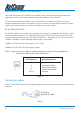
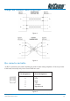
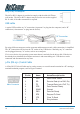
Table Of Contents
- Contents
- Overview
- NB5 Package Contents Note
- Minimum System Requirements
- Front Indicators
- Back Panel
- Resetting Factory Defaults
- Do I need a Micro filter?
- Default Settings
- Quick Start Guide
- Connecting your NB5 ADSL Modem via ETHERNET
- Connecting your NB5 ADSL Modem via USB
- Setting up your ADSL Router
- Log into your ADSL Router
- Quick Start Menu
- Connecting your ADSL Router
- Step 1: Connecting the ADSL Router to Your Computer/Notebook
- Step 1.1 Connecting to the Ethernet/USB
- Step 1.2 Connecting to the ADSL Line
- Step 1.3 Connecting to the Power Outlet
- Step 1.4 Powering On
- Step 2: Configuring Your Ethernet Network Card / Installing Your USB Device
- 2.1 Configuring Your Ethernet Network Card
- 2.2 Installing the USB Device Driver
- Step 3: Configuring Your Internet Browser
- Step 4: Connecting to the Internet
- Firewall Configuration
- Introduction to Firewalls
- Network Address Translation and Port Mapping
- Dedicated Firewalls
- Advanced Configuration of your ADSL Router
- Log into your ADSL Router
- Advanced Configuration of your ADSL Router-Login Settings
- Advanced Menus
- Introduction to Setup and Advanced Menus
- Configuring the ADSL Connection
- The Setup Menu
- WAN Setup
- PPPoE Connection
- PPPoA Connection Setup
- DHCP Connection Setup
- Static Connection Setup
- Bridged Connection Setup
- CLIP [Classical IP over ATM] Connection Setup
- LAN Setup
- DHCP Configuration
- Management IP
- The Advanced Menu
- UPnP
- SNMP
- IP QoS
- LAN Clients
- MAC Filter Control
- Enable/Disable MAC Filtering
- Create MAC Filter Rules
- Edit or Delete MAC Filter Rules
- Hidden MAC Filter Rules
- Multicasting
- Static Routing
- Dynamic Routing
- Port Forwarding
- Access Control
- IP Filters
- DMZ Configuration
- Tools Menu
- System Commands
- User Management
- Update Firmware
- Ping Test
- Modem Test
- Reboot
- Log Out
- Status Menu
- Network Statistics
- Connection Status
- DHCP Clients
- Modem Status
- Product Information
- System Log
- Appendix A: Troubleshooting
- The ADSL Router is not functional
- I can't connect to the ADSL Router.
- The DSL Link LED continues to blink but does not go solid
- The DSL Link LED is always off
- Appendix B: ADSL Router terms
- What is a firewall?
- What is NAT?
- What is a DMZ?
- What is a Gateway?
- Appendix C: Features
- ADSL/ATM Support
- Encapsulation Support
- Network Support
- Management Support
- Security Support
- External Connectors:
- Appendix D: Cable Connections
- RJ-45 Network Ports
- Twisted pair cables
- Straight and crossover cable configuration
- RJ11 connector and cable
- 605 to RJ-11 adapter
- USB cable
- 9 Pin (RS-232 ) Serial Cable
- Appendix E: Registering your NetComm Product
- Contact Information
- Legal & Regulatory Information
- Product Warranty
NetComm NB5 Ethernet/USB Modem Router YML717 Rev1
78 www.netcomm.com.au
Appendix D: Cable Connections
This cable information is provided for your reference only. Please ensure you only connect the
appropriate cable into the correct socket on either this product or your computer.
If you are unsure about which cable to use or which socket to connect it to, please refer to the
hardware installation section in this manual. If you are still not sure about cable connections, please
contact a professional computer technician or NetComm for further advice.
RJ-45 Network Ports
RJ-45 Network Ports can connect any networking devices that use a standard LAN interface, such as
a Hub/Switch Hub or Router. Use unshielded twisted-pair (UTP) or shield twisted-pair (STP) cable
to connect the networking device to the RJ-45 Ethernet port. Depending on the type of connection,
10Mbps or 100Mbps, use the following Ethernet cable, as prescribed.
10Mbps: Use EIA/TIA-568-100-Category 3, 4 or 5 cable.
100Mbps: Use EIA/TIA-568-100-Category 5 cable.
Note: To prevent loss of signal, make sure that the length of any twisted-pair
connection does not exceed 100 metres.
Figure 1
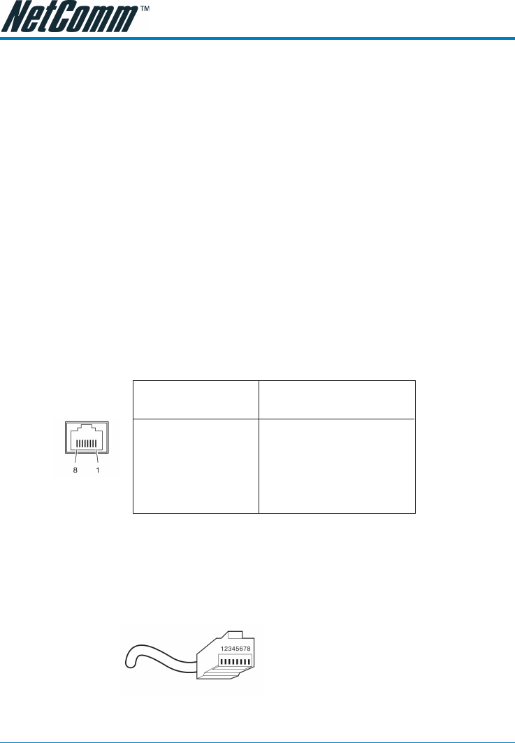
Twisted pair cables
Figures 1 and 2 illustrate the use of straight-through and crossover twisted pair cables along with the
connector.
Figure 2
RJ-45 plug
attached to cable
RJ-45 Connector
Pin Assignment Normal Assignment
1 Input Receive Data +
2 Input Receive Data -
3 Output Transmit Data +
6 Output Transmit Data -
4,5,7,8 Not used