Legal & Regulatory Information This manual is copyright. Apart from any fair dealing for the purposes of private study, research, criticism or review, as permitted under the Copyright Act, no part may be reproduced, stored in a retrieval system or transmitted in any form, by any means, be it electronic, mechanical, recording or otherwise, without the prior written permission of NetComm Limited. NetComm Limited accepts no liability or responsibility, for consequences arising from the use of this product.
Contents Overview .................................................................................................................................................................. 6 NB5 Package Contents Note .............................................................................................................. 7 Minimum System Requirements ......................................................................................................... 8 Front Indicators .....................................
The Setup Menu ..................................................................................................................................................... 37 WAN Setup ....................................................................................................................................... PPPoE Connection ..................................................................................................................... PPPoA Connection Setup ........................................
Product Information ........................................................................................................................... 71 System Log ....................................................................................................................................... 71 Appendix A: Troubleshooting ................................................................................................................................ 72 The ADSL Router is not functional .....................
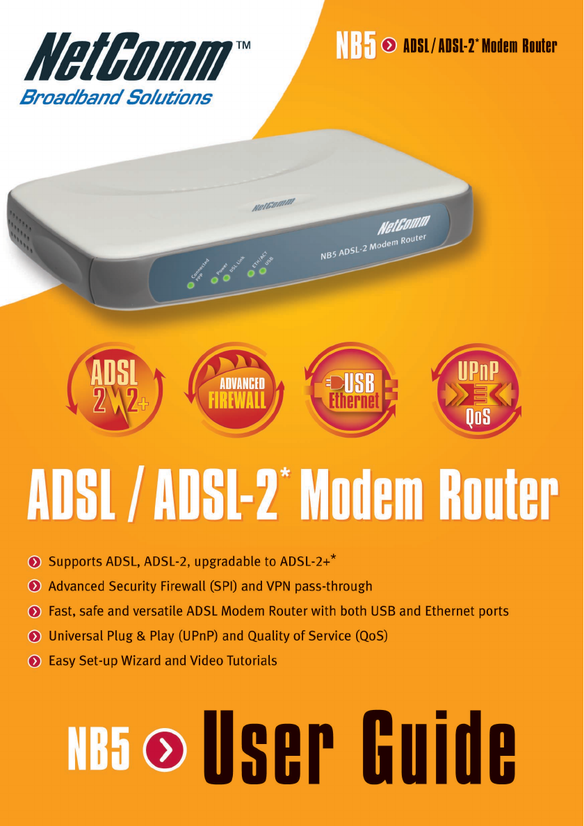
Overview Overview Thank you for purchasing the NetComm NB5 ADSL/ADSL2 Modem Router. NetComm brings you the Next Generation of ADSL technology with ADSL-2*, which boosts ADSL's performance, improves interoperability, and supports new applications, services and deployment conditions. NetComm’s implementation of ADSL-2* and ADSL-2+* ensures that the NB5 operates with existing ADSL services while delivering optimal performance in all modes of operation.
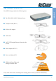
NB5 Package Contents Note Your NB5 Package contains the following items: Overview ■ The NB5 ADSL/ADSL-2 Modem Router ■ Telephone cable (RJ-11) ■ RJ11 to 605 Adaptor ■ USB Cable ■ CAT-5 UTP Straight Ethernet Network cable (RJ-45) ■ Power adapter (DC 9V) ■ Driver and Manual CD ■ NB5 Quick Start Guide and Package Contents Note If any of the above items are damaged or missing, please contact your dealer immediately. YML717 Rev1 www.netcomm.com.
Minimum System Requirements Overview Before continuing with the installation of your NB3, please confirm that you comply with the minimum system requirements.
Front Indicators Overview Connected PPP Lights up when the Internet (PPP) connection is established. Power Lights up when power is supplied to the Router. DSL Link Lights up when the ADSL connection is established. Flickers when the ADSL Router is trying to establish a connection with the ADSL Service Provider. ETH/ACT Lights up when the Ethernet cable is properly connected from your Router to the Ethernet Card.
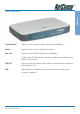
Overview Back Panel ADSL Telephone jack (RJ-11) to connect to your Telephone Wall Socket (ADSL line). USB USB port to connect to the USB port on your computer/notebook. ETHERNET 10/100 Base-T Ethernet jack (RJ-45) to connect to your Ethernet Network card or Ethernet Hub / Switch. RESET To reset your ADSL Router to factory default settings. (All customised settings that you have saved will be lost!) Please refer to the section below on how to use the reset function.
Do I need a Micro filter? Splitters may be installed when your ADSL line is installed or when your current phone line is upgraded to ADSL. If your telephone line is already split you will not need to use a Microfilter check with your ADSL service provider if you are unsure. Each micro filter is connected in-line with your telephone or fax machine so that all signals pass through it. Telephones and/or facsimiles in other rooms that are using the same extension will also require Microfilters.
Default Settings Overview LAN (Management) Field Setting Details Static IP Address: 192.168.1.1 ❖ Subnet Mask: 255.255.255.0 ❖ Default Gateway: blank WAN (Internet) Field Setting Details User Name: username Password: **** Protocol: PPPoE VPI: 8❖ VCI: 35 ❖ IP Address: 192.168.1.1 ❖ Subnet Mask: 255.255.255.0 ❖ Default Gateway: 0.0.0.0 ❖ Bridge mode: Enabled Modem Access ❖ Field Setting Details User Name: admin Password: admin Default Setting.
Quick Start Guide The NB5 can be connected via a USB cable or an Ethernet cable or both. The reason for this is that the USB connection is simply an ethernet simulation, as far as your computer is concerned the USB connection is an Ethernet connection, hence DHCP and other protocols will work the same as for Ethernet. To connect to your ADSL Router, you need to have either an Ethernet Port or a USB Port present on your Computer/Notebook. 1.
Quick Start Guide Connecting your NB5 ADSL Modem via USB 1. Connect the power pack to the NB5 ADSL Modem and switch on the power switch. 2. Connect your NB5 to a computer directly via USB cable. 3. When the computer is booted, the Add New Hardware Wizard will launch and prompt you to provide a driver for your NB5 ADSL Modem. Insert the CD ROM provided. 4. Follow the on-screen prompts to load the driver. Refer to the section below for more detailed information. (You may need to restart your computer). 5.
Setting up your ADSL Router This section will guide you through your ADSL Router's configuration. Before continuing, please ensure that your ADSL line is connected to your NB5 ADSL Router and that your router is connected to your computer. Log into your ADSL Router To access the NB5 ADSL Router configuration screens: 2. Type the default IP address http://192.168.1.1 and press Enter to open the Log In screen. 3.
Quick Start Menu Quick Start Guide The first screen that appears (after the log in screen) is the Quick Start screen. By default the NB5 ADSL Router has been configured to use a PPPoE connection, and you usually only need to enter the username and password (as specified by your ISP) to make a connection to the internet. The Quick Start wizard is meant for basic users to allow easy and seamless connectivity to the internet without worrying about any other advanced configuration settings.
Connecting your ADSL Router Step 1: Connecting the ADSL Router to Your Computer/Notebook To connect to your ADSL Router, you need to have either an Ethernet Port or a USB Port present on your Computer/Notebook. Step 1.1 Connecting to the Ethernet/USB (See the note on the following page if you are not sure of what the Ethernet and USB Port looks like) 1.1.1 For Single-User Connection The following shows a typical single-user connection. ■ If an Ethernet Port is present, please proceed to section 1.1.
1.1.2 For Multiple User Connections Connection You may connect one computer/notebook to the Ethernet Port and another one to the USB Port on the ADSL Router at the same time. Refer to both section 1.1.2(a) Connecting to the Ethernet and section 1.1.2(b) Connecting to the USB for the connections. For more than 2 Computers/Notebooks connections, you may also expand the Ethernet connection by connecting the ADSL Router to an Ethernet Switch/Hub.
1.1.1(a) For Single User Connection (This connection is not required if you are connecting to an Ethernet Switch/Hub for multiple user connections). 1.1.1(b) Connecting to the USB NOTE: Your computer should be powered down before insertion of the USB cable. For a single user connection, you may now proceed to Step 1.2. YML717 Rev1 www.netcomm.com.au NetComm NB5 Ethernet/USB Modem Router 19 Connection For single-user connection, you may now proceed to Step 1.
Step 1.2 Connecting to the ADSL Line Connect your ADSL Router to the ADSL line with the telephone cable. If you are connecting a telephone or facsimile to the same line, refer to the section on Microfilters for more information. Step 1.3 Connecting to the Power Outlet Connect your ADSL Router to the Power Outlet via the Power adapter (that comes with your ADSL Router package). Step 1.4 Powering On Power on the Power Outlet that is connected to your ADSL Router. Power on your Computer(s)/Notebook(s).
Step 2: Configuring Your Ethernet Network Card / Installing Your USB Device ✎ 2.1 If your computer/notebook is connected to the Ethernet Port of the ADSL Router, proceed with section 2.1. If your computer/notebook is connected to the USB Port of the ADSL Router, proceed with section 2.2. If your computers/notebooks are connected to both the Ethernet Port and USB Port of your ADSL Router, please proceed with both sections 2.1 and 2.
iii Click the IP Address tab. Click the option Obtain an IP address automatically and click OK to save the settings. Connection Ensure that your ADSL Router is powered on. Restart your system. Proceed to Step 3. 2.1.2 For Windows® 2000 / Windows® XP Windows® 2000: a) From your Windows desktop, right-click on the icon My Network Places and select Properties. b) At the Network and Dial-up Connections window, right-click on the Local Area Connection icon and select Properties.
Ensure that the field Connect Using indicates the model of your Ethernet Card that is connected to your ADSL Router. (This is important especially if you have more than one Local Area Connection icons displayed at the Network and Dial-up Connections / Network Connections window. Ensure that you have selected the correct one.) Select the option Obtain an IP address automatically and click OK. Click OK again to close. Ensure that your ADSL Router is powered on. Restart your system. Proceed to Step 3.
2.2 Installing the USB Device Driver 1. Proceed with this section ONLY if your computer/notebook is connected to the USB Port of your ADSL Router! 2. The following screen shots illustrated serve only as examples. For any dissimilarities, please follow closely the instructions prompted on your Computer/Notebook. 3. For Windows® 98 Second Edition users, you may be prompted for your Windows CD-ROM. Have it ready by your side. 2.2.
Click CD-ROM drives option and click Next. vi Select ‘The updated driver (Recommended) DSL Router USB Remote NDIS Network Device’ and click Next. vii Click Next to proceed installation with the indicated driver. Connection v Depending on your system configurations, you may be prompted for your Windows CD-ROM during installation. At the prompt, replace the Installation CD in your CD-ROM Drive with your Windows CD-ROM and click OK.
Connection 2.2.2 Installing the USB Device Driver - For Windows® Me i Power on your computer to start Windows. ii Place the Installation CD into your CD-ROM Drive. iii At the following prompt, select ‘Specify the location of the driver (Advanced)’ and click Next. iv Click the ‘Removable Media’ option and click Next. v Click Next again to proceed installation with the indicated driver. vi Click Finish to complete the USB driver installation. vii Restart your system when prompted.
2.2.3 Installing the USB Device Driver - For Windows® 2000 Power on your computer to start Windows. ii Place the Installation CD into your CD-ROM Drive. iii At the following prompt, click Next. iv Select ‘Search for a suitable driver for my device (recommended)’ and click Next. v Click CD-ROM drives option and click Next. vi At the next prompt, click Next to proceed installation with the indicated driver. vii You may encounter a 'Digital Signature Not Found' dialog box during installation.
Click Yes to proceed with the installation. viii 2.2.4 Click Finish when prompted. Upon completion, proceed to Step 3. Installing the USB Device Driver - For Windows® XP Power on your computer to start Windows. ii Place the Installation CD into your CD-ROM Drive. iii At the following prompt, select Install from a list or specific location (Advanced) option and click Next. iv Click ‘Search removable media’ and click Next. v Click Finish, then proceed to Step 3.
Step 3: Configuring Your Internet Browser 3.1 Microsoft® Internet Explorer™ (based on IE 5.5) i From your Windows desktop, double-click on your Internet Explorer icon to launch your Browser. ii From the Menu, click Tools and select Internet Options... . iii Select the Connection tab. Click the field, 'Never dial a connection'. (This option will be grayed off if you have not installed an analog modem on your computer/ notebook before. Proceed with 3.1 iv). iv Click the LAN Settings... button.
Step 4: Connecting to the Internet i NOTE: From your Internet Browser, type in http://192.168.1.1 and hit . The NB5 Admin username and password is not the same as the username and password provided by your ISP to connect to the Internet ii You will be prompted for the username and password to login to the Web Management. Enter admin for both the username and password field . Click OK.
Firewall Configuration Introduction to Firewalls The NB5 is equipped with advanced Firewall features to provide security from malicious attack, hacking or eavesdropping across the Internet. The following information is provided as an introduction to firewalling and to the techniques that can be used to selectively enable services across the firewall while still maintaining security. Network Address Translation and Port Mapping The NB5 is a NAT router.
The Default Setting of the NB5 does not provided access from the Internet to any services hosted on the LAN. In other words, by default the firewall function is fully enabled and the only incoming packets allowed are those elicited by a request from a LAN client. The NB5 Access Control function allows selective access to services through the Firewall, categorised by service type (Web, FTP, Telnet, etc) and optionally filtered by IP address.
Advanced Configuration of your ADSL Router This section will guide you through your ADSL Router's configuration. Before continuing, please ensure that your ADSL line is connected to your NB5 ADSL Router and that your router is connected to your computer. Log into your ADSL Router To access the NB5 ADSL Router configuration screens: 1. Open your web browser. 2. Type the default IP address http://192.168.1.1 and press Enter to open the Log In screen. 3.
Advanced Configuration of your ADSL Router-Login Settings The first screen that appears (after the log in screen) is the Quick Start screen. By default the NB5 ADSL Router has been configured to use a PPPoE connection, and you usually only need to enter the username and password (as specified by your ISP) to make a connection to the internet.
Advanced Menus Please note: Throughout this manual the term 'WAN' - Wide Area Network - will denote the ISP side of a broadband internet connection, and the term 'LAN' - Local Area Network - will refer to the home/office side of the connection.
Configuring the ADSL Connection ADSL connections can be configured in a variety of ways depending on the ISP/WAN configuration, and the requirements of your home or office LAN.
The Setup Menu The NB5 can be configured to maintain up to eight Connection Profiles. Different Connection Profiles may be required if you connect to more than one ADSL service provider, or if you vary the connection type you use, or if your NB5 is used in different locations. The NB5 Interface provides a function under the WAN Setup Menu to enable the user to create, save and select Connection Profiles as required. (Note than in many cases, only one connection profile will be required.
PPPoE Connection Point-to-Point Protocol [=PPP] is a method of establishing a network connection between network hosts. PPPoE, also known as RFC 2516, adapts PPP to work over Ethernet for ADSL connections. Among other things, PPPoE provides a mechanism for authenticating users by providing User Name and Password fields and is a connection type provided by many ISPs. To setup PPPoE, select WAN Setup >New Connection.
Select the encapsulation type [LLC or VC]; if in doubt leave as default. Select the VPI and VCI settings: 8/35 is default [recommended]. Username: Your ISP account ID e.g. Password: ISP Account Password On-Demand: Enables on-demand mode. The connection will be dropped if no activity is detected after the specified idle timeout value [see next]. Idle Timeout: Specifies that PPPoE connection should disconnect if the link has no activity detected for n seconds [see above].
PPPoA Connection Setup Point-to-Point Protocol [=PPP] is a method of establishing a network connection between network hosts. PPPoA, also known as RFC 2346, adapts PPP to work over ATM cells for ADSL connections. Among other things, PPPoE provides a mechanism for authenticating users by providing User Name and Password fields. Many ISPs support PPPoA connection types. To setup PPPoA, select WAN Setup >New Connection. From Type: select PPPoA. This will reveal the PPPoA Connection Setup screen.
Select the encapsulation type (LLC or VC) according to information is provided by the ISP. Select the VPI and VCI settings: 8/35 is default [recommended]. Username: Your ISP account ID e.g. Password: ISP Account Password On-Demand: Enables on-demand mode. The connection will be dropped if no activity is detected after the specified idle timeout value [see next].
DHCP Connection Setup Dynamic Host Configuration Protocol (DHCP) allows the ADSL Router to automatically obtain the IP address from the server. This option is commonly used in situations where the IP address is dynamically assigned and is not known prior to assignment. To setup DHCP, select WAN Setup >New Connection. From Type: select DHCP. This will reveal the DHCP Connection Setup screen. Enter the DHCP connection name: the name must be unique, must not contain spaces and must not begin with a number [e.
Select the VPI and VCI settings: 8/35 is default [recommended]. If your DSL line is connected and the Service Provider is providing DHCP, click the Renew button and the gateway will retrieve the IP Address, Subnet mask, and Gateway address. At any time, you can renew the DHCP address by clicking on the renew button but this is not generally necessary as the process runs automatically.
Static Connection Setup Most Internet users are provided with a dynamic IP address by their ISP for each session, however certain situations call for a Static IP address. This is typically when you want to host a website, or use VoIP or video-conferencing applications where other users must regularly connect to your computer. Static IP numbers are generally made available by ISPs for these purposes for an additional fee.
Static Settings Encapsulation: LLC or VC: provided by ISP. Enter the Static IP Address provided by the ISP Enter the Subnet mask and the Default Gateway as specified by the ISP. Up to three Domain Name Server (DNS) addresses can also be specified. For static configuration, you can also select a bridge connection or a routed connection. Since a Static IP address is typically used to host WEB servers, Bridged connection is usual however Routed is provided also: check with ISP for confirmation.
Bridged Connection Setup A Bridged connection basically disables the routing, firewall and NAT features of the NB5. In a Bridged connection, the NB5 acts as a modem or hub, and just transmits packets between the WAN interface and the LAN interface. A Bridged connection assumes that another device is providing the routing functionality that is now disabled in the NB5. To setup a Bridged Connection, select WAN Setup >New Connection. From Type: select Bridge.
Select the Quality of Service [QoS] type; if in doubt leave as default. To complete and save the Connection Profile, click the Apply button, and then click on Save Settings at the bottom of the menu list on left. Advanced YML717 Rev1 www.netcomm.com.
CLIP [Classical IP over ATM] Connection Setup The Classical IP over ATM (CLIP) support provides the ability to transmit IP packets over an ATM network, CLIP support will encapsulate IP in an AAL5 packet data unit (PDU) frame using RFC1577and utilizes an ATM-aware version of the ARP protocol. To setup a CLIP connection, select WAN Setup >New Connection. From Type: select CLIP. This will reveal the CLIP Connection Setup Screen.
Select the Quality of Service [QoS] type; if in doubt leave as default. Clip Settings: IP Address, Mask and Default Gateway: Provided by ISP ARP Server: Leave as Default [0.0.0.0] unless advised by ISP. Modifying or Deleting a Saved Connection To modify a previously-defined Connection Profile, select WAN Setup>Connection. Click on the Connection Name that you wish to modify or delete.
LAN Setup DHCP Configuration To access the DHCP Configuration Screen, click Setup>LAN Setup>DHCP Configuration. Server On The Server On radio button enables the NB5 DHCP function. For DHCP functionality to work properly the following rules must be observed. Advanced Start IP - End IP Range The Start IP Address indicates the beginning of the range at which the DHCP server starts issuing IP addresses. This value must be greater than the Routers IP address value. So if the Routers IP address is 192.168.1.
If the total number of network nodes is greater than the range of available IP addresses, the DHCP server will run out of DHCP addresses, and some users will not get access to network resources. If this happens you can either (1) increase the Ending IP address (to the limit of 255) or (2) reduce the Lease Time. (see below) Caution: If you change the Start IP or End IP values, ensure the values are still within the same subnet as the Routers' IP address. In other words, if the Routers' IP address is 192.
By default, your ADSL Router has DHCP server (LAN side) enabled. This function will allocate DHCP numbers to any network node on your LAN as required according to the settings above. However, if you already have a DHCP server running on your network, you must disable one of the two DHCP servers as the presence of two DHCP servers on one LAN will create conflicts and lead to network problems. To disable the DHCP function on the NB5, select the Server and Relay Off radio button.
The Advanced Menu The Advanced Menu provides access to advanced networking and routing capabilities including security, port configuration and UPnP UPnP Universal Plug and Play [UPnP] is a protocol which automates connectivity between network devices, including computers, game consoles, digital cameras, PDAs and other systems which connect via TCP/IP. Applications which implement the UPnP protocol are able to negotiate a connection with a UPnP-enabled device without requiring manual device configuration.
SNMP Simple Network Management Protocol is a system which allows management of multiple remote devices from a central location. To access SNMP, click on Advanced>Advanced Features>SNMP. Advanced To save changes, click on Apply, then click on Save Settings. NetComm NB5 Ethernet/USB Modem Router 54 YML717 Rev1 www.netcomm.com.
IP QoS ABOUT: IP Quality of Service (QoS) prioritises data streams to ensure that basic connectivity is maintained when running multiple services over one connection. For example, if you are using a peer-to-peer file-sharing program at the same time as performing normal web browsing, you can configure QoS to limit the resources dedicated to the peer-to-peer session in order to ensure web browser connectivity. QoS is often vital to maintain VoIP session quality.
LAN Clients ABOUT: LAN Client names are a way of applying specific Port-forwarding, Access Control and QoS rules to individual computers on the LAN. If DHCP is used, all DHCP clients are automatically assigned and are designated as a LAN client. Advanced To add a LAN client, click Advanced>Advanced Features>LAN Clients. NetComm NB5 Ethernet/USB Modem Router 56 YML717 Rev1 www.netcomm.com.
MAC Filter Control MAC filtering enables rules to be defined which allow or deny data to pass through the Router based on the source and destination MAC address and data type of each data frame. To access MAC Filters Control, click on Advanced>Advanced Features>MAC Filters .
Create MAC Filter Rules Enter the Source MAC and Destination MAC details. Entering zeros or blanks into the Source or Destination fields enters a null value. 'Protocol' provides the choice of protocol type for the rule. 'Mode' provides the choice of Allow or Deny for the rule. When all selections are made, click on Add to add the rule to the list of rules. A maximum of 20 MAC Filter Rules can be defined and saved. To save changes, click on Save Settings on the left-hand menu.
Multicasting IGMP [=Internet Group Management Protocol] Multicast enables communication between a single sender and multiple receivers on a network. It is used when data needs to be sent from one to many devices. Typical uses might include the updating of mobile personnel from a home office or the periodic publishing of an online newsletter. Multicasting provides efficiencies which enable it to use less network bandwidth than the sending of the same data by other means [e.g. SMTP].
Static Routing If the Router is required to serve more than one network, you will need to set up a Static Route between the networks. Static routing can be used to allow users from one IP domain to access the Internet through the Router in another domain. A Static Route provides the defined pathway that network information must travel to reach the specific host or network which is providing Internet access . To access the Static Routing controls, click on Advanced>Advanced Features> Static Routing.
Dynamic Routing Dynamic Routing makes use of the RIP Protocol to allow the ADSL Router to automatically adjust to physical changes in the network. The NB5, using the RIP protocol, will determine the network packet route based on the fewest number of hops between the Source and the Destination. The RIP protocol regularly broadcasts routing information to other ADSL Routers on the network and is part of the IP Suite. To access Dynamic Routing click Advanced>Advanced Features>Dynamic Routing.
Port Forwarding Port Forwarding is necessary because NAT [=Network Address Translation] only forwards traffic from the Internet to the LAN if a specific port mapping exists in the NAT translation table. Because of this, the NAT provides a level of protection for computers that are connected to your LAN. However, this also creates a connectivity problem when you want to make LAN resources available to Internet clients, which you may want to do to play network games or host network applications.
Easy Port Forwarding: Applying Pre-Defined Rules WAN Connection: refers to the active Connection Profile. LAN IP: refers to the local Router IP address; the NB5 Default IP is shown in this example. New IP: If you wish to manually add a LAN client so that you can apply rules to it, click on the New IP Button and enter Host Name and IP Address. Available pre-defined rules are categorised according to the application type.
To create a New Port Forward Rule: On the Port Forwarding page shown in the figure above, click on the User radio button, then on the New Button. Rule Name: enter a name that identifies the rule; for the sake of clarity this will usually be the name of the application. The name must be unique, must not contain spaces and cannot begin with a number. Protocol: can be either TCP or UDP, or both. Port start…port end: These will be the same if you are forwarding only a single port.
Access Control Use Access Control to configure advanced security functions by customising the NB5 Firewall. The default 'Firewall On' setting blocks all anonymous Internet traffic. Access control enables the user to selectively direct such traffic, for example to a Web Host in the DMZ or to specific ports opened for such applications as Web, Telnet or FTP. CAUTION: This dialog box indicates that you should not disable LAN Web Access or else you might not be able to connect to the device.
Enable Access Control: check this box to enable selective access from the WAN to your LAN for applications of the class indicated by the relevant check boxes. If Access Control is not enabled, the individual check boxes cannot be checked. If Access Control is enabled, and an Enable WAN checkbox is selected, then WAN access to the matching service is enabled.
IP Filters The IP filters page allows you to specify Normal Port Forwards, Block ALL traffic to specific LAN Clients or specify Custom IP filters that will control the flow of data across the router.
DMZ Configuration A DMZ (demilitarized zone) is a computer host or small network inserted as 'neutral territory' between a private LAN and the Internet. It prevents outside users from getting direct access to LAN computers while still being able to access services hosted on the designated DMZ Computer. When using NAPT to share your internet connection, LAN computers will still be able to access the Internet when the DMZ host is enabled.
Tools Menu System Commands To access System Commands, Click on Tools>System Commands. Save All: Press this button in order to permanently save the current configuration of the Gateway. If you do re-start the system without saving your configuration, the Gateway will revert back to the previously saved configuration. Restart: Use this button to re-start the system. If you have not saved your configurations, the Gateway will revert back to the previously saved configuration upon re-starting.
Update Firmware 'Firmware' is the software that controls the NB5 and also provides the user interface that is the subject of this manual. The Firmware resides in the NB5 internal memory; currently loaded firmware version can be found under Status>Product Information. Firmware upgrades may be offered from time to time by NetComm Ltd. as required. It is strongly recommended that you only upload firmware that is supplied by NetComm Ltd. Available firmware updates will be posted on www.netcomm.com.au.
Status Menu About: The Status Menu provides dynamically-updated information about your DSL connection, modem and network performance. Network Statistics To access network statistics, click on Status>Network Statistics. Select Network Interface type to peruse statistics for each type of connection. Connection Status To access Connection Status, click on Status>Connection Status.
Appendix A: Troubleshooting Below is a list of commonly asked questions. Before calling technical support, please look through these issues to see if they help to solve your problem. The ADSL Router is not functional 1. Check to see that the power LED is green and than the network cables are installed correctly. Refer to the easy start guide for more details. 2. Check to see that the ETH/LAN and PPP/WAN LEDs are green. 3. Check to see that the DSL LED is green 4. Check the settings on your PC.
4. If this still does not work, press the reset button for 10 seconds. This will place the gateway into its factory default state. Go through the above procedures again. 5. Make sure NAT is enabled for your connection. If NAT is disabled the ADSL Router will not route frames correctly (except in Bridge connection). The DSL Link LED continues to blink but does not go solid 1. This means that the DSL line is trying to train but for some reason it cannot establish a valid connection.
Appendix B: ADSL Router terms What is a firewall? A firewall is protection between the Internet and your local network. It acts similarly to the firewall in your car, protecting the interior of the car from the engine. Your car's firewall has very small opening that allow desired connections from the engine into the cabin (gas pedal connection, etc), but if something happens to your engine, you are protected. The firewall in the ADSL Router is very similar.
What is a Gateway? The Internet is so large that a single network cannot handle all of the traffic and still deliver a reasonable level of service. To overcome this limitation, the network is broken down into smaller segments or subnets that can deliver good performance for the stations attached to that segment. This segmentation solves the problem of supporting a large number of stations, but introduces the problem of getting traffic from one subnet to another.
Appendix C: Features ADSL/ATM Support ■ ANSI T1.413 issue 2, ITU-T G.992.1 (G.dmt) and G.992.2 (G.
■ Single Session IP Sec and PPTP/L2TP VPN pass through support ■ PPP Always on with configurable timeout ■ PPP Dial on Demand ■ Universal Plug and Play Support Management Support ■ Web Based HTTP management GUI ■ TFTP/FTP Support for Firmware Upgrade ■ Web Based Firmware Upgrade (Local) ■ Soft Factory Reset Button via Web GUI ■ Diagnostic Test (DSL, OAM, Network, Ping Test) ■ Telnet/CLI (Read Only) ■ Syslog Support Security Support ■ NAT for basic Firewall support ■ Packet Filtering Firewall Support ■ Sta
Appendix D: Cable Connections This cable information is provided for your reference only. Please ensure you only connect the appropriate cable into the correct socket on either this product or your computer. If you are unsure about which cable to use or which socket to connect it to, please refer to the hardware installation section in this manual. If you are still not sure about cable connections, please contact a professional computer technician or NetComm for further advice.
Straight and crossover cable configuration Figure 3 Figure 4 RJ11 connector and cable An RJ-11 connector is the small, modular plug used for most analog telephones. It has six pin slots in the head, but usually only two or four of them are used. RJ-11 Connector Pin Assignment 1 2 3 4 5 6 Normal Assignment Signal Ground CTS RXD TXD +5 Volts In Signal Ground Figure 5 YML717 Rev1 www.netcomm.com.
605 to RJ-11 adapter The 605 to RJ-11 adaptor is provided to comply with the older 610 Telstra wall socket. The 605 to RJ-11 adapter may be used to convert the supplied RJ-11 cable, if the older connection is required. USB cable A typical USB cord has an "A" connection (“upstream” to plug into the computer) and a “B” connection (“downstream” to plug into the device). “B” Connection “A” Connection By using different connectors on the upstream and downstream ends, cable connection is simplified.
Appendix E: Registering your NetComm Product All NetComm Limited (“NetComm”) products have a standard 12 month warranty from date of purchase against defects in manufacturing and that the products will operate in accordance with the specifications outlined in the User Guide. However some products have an extended warranty option (please refer to packaging).
Legal & Regulatory Information This manual is copyright. Apart from any fair dealing for the purposes of private study, research, criticism or review, as permitted under the Copyright Act, no part may be reproduced, stored in a retrieval system or transmitted in any form, by any means, be it electronic, mechanical, recording or otherwise, without the prior written permission of NetComm Limited. NetComm Limited accepts no liability or responsibility, for consequences arising from the use of this product.
Product Warranty The warranty is granted on the following conditions: 1. This warranty extends to the original purchaser (you) and is not transferable; 2. This warranty shall not apply to software programs, batteries, power supplies, cables or other accessories supplied in or with the product; 3. The customer complies with all of the terms of any relevant agreement with NetComm and any other reasonable requirements of NetComm including producing such evidence of purchase as NetComm may require; 4.