Installation Guide NetBotz® USB Coordinator & Router NBWC100U
Contents Introduction. . . . . . . . . . . . . . . . . . . . . . . . . . . . . . . . . . . . . . . . . . . 1 Product description . . . . . . . . . . . . . . . . . . . . . . . . . . . . . 1 Document overview . . . . . . . . . . . . . . . . . . . . . . . . . . . . . 1 Additional documentation . . . . . . . . . . . . . . . . . . . . . . . . . 1 Supported appliances . . . . . . . . . . . . . . . . . . . . . . . . . . . 2 Supported devices on the NetBotz wireless network . . . . 2 Physical Description . . . . .
Two Year Limited Factory Warranty . . . . . . . . . . . . . . . . . . . . . . 17 Obtaining service . . . . . . . . . . . . . . . . . . . . . . . . . . . . . .
NetBotz USB Coordinator & Router Installation iii
iv NetBotz USB Coordinator & Router Installation
Introduction Product description The NetBotz® USB Coordinator & Router connects to a NetBotz appliance and allows you to monitor the temperature and humidity in your data center using the NetBotz Wireless Temperature Sensor (NBWS100T and NBWS100H). Additionally, you can use a Wireless Sensor Pod 180 (NBPD0180) to monitor multiple temperature readings and rack door access. The USB Coordinator & Router can be configured as the Coordinator or as a Router in your wireless sensor network.
Supported appliances You can connect the USB Coordinator & Router to a wireless sensor network on any of the following appliances: • NetBotz Rack Monitor 450 (NBRK0450) • NetBotz Room Monitor 455 (NBWL0455, NBWL0456) • NetBotz Rack Monitor 550 (NBRK0550) • NetBotz Rack Monitor 570 (NBRK0570) The NetBotz Rack Monitor 450 appliance supports a total of 26 wireless devices on the wireless sensor network.
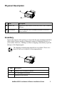
Physical Description Item Description Status LED Signifies the mode and the current state of the USB Coordinator & Router Reset button Used to reboot the USB Coordinator & Router or reset it to factory defaults Inventory Inspect the contents of the package to ensure that the parts included match those shown below. Report missing or damaged contents to Schneider Electric or your reseller. However, if damage was due to shipping, immediately report the damage to the shipping agent.
Components of the Wireless Sensor Network The USB Coordinator & Router can be configured to act in two different modes on a wireless sensor network: Coordinator or Router. The mode of a USB Coordinator & Router is determined by the manner in which power is supplied to the device. The factory default is Router mode. Host Appliance. A wireless sensor network is monitored by a single NetBotz appliance, listed in “Supported appliances” on page 2.
Note: For information about using the Wireless Temperature Sensor or the Wireless Sensor Pod 180 on your wireless network, see the installation manual that came with the product.
Installing the Wireless Sensor Network Overview The order in which you power and configure your wireless network is important. For best results, power and configure your wireless network as follows: Scan the extended address (MAC) of each USB Coordinator & Router.
Power the Coordinator. Power the Coordinator FIRST. Connect one and only one USB Coordinator & Router to a USB Type A port on the NetBotz appliance. Power the Routers. Power each Router using the included AC-USB adapter, not directly connected to the NetBotz appliance. Power the End Devices. To power the Wireless Temperature Sensor, turn it on using the rocker switch on its side. To power the Wireless Sensor Pod 180, insert the included batteries.
Positioning the USB Coordinator & Router When planning your installation locations, be sure to place each USB Coordinator & Router within range of the Coordinator or another Router. The maximum wireless range of the USB Coordinator & Router is 100 ft (line of sight). This range is a best-case scenario and the signal will be strongly affected by environmental interference. Use the RSSI sensor reading (available in the device’s sensor listing in Advanced View) to tune device placement.
Powering the Coordinator Power the Coordinator first. Connect one and only one Coordinator to a USB Type A port on the NetBotz appliance. The USB Coordinator & Router will be automatically configured in Advanced View as the Coordinator on your wireless sensor network. Once the Coordinator is running, the other devices in the wireless sensor network will join the network automatically as long as their extended addresses are in the commission list, and they are powered.
To add a different device to become the Coordinator: 1. Connect a USB Coordinator & Router or Wireless Sensor Pod 180 to a USB Type A port on the NetBotz appliance. 2. Click Add. 3. Enter the extended address (MAC) of the new Coordinator. 4. Click Apply Commission List to save the list to the NetBotz appliance. 5. If a Wireless Sensor Pod 180 is used as the new Coordinator, click Configure Coordinator to identify its serial port ID and specify its port label.
LED activity The LED on the USB Coordinator & Router flashes to indicate certain statuses or alerts. Boot process LED Activity Flashes a quick green, yellow, red sequence Alternately flashes green and yellow for about 45 seconds Flashes green three times Turns solid yellow for 5 seconds Flashes a quick green, yellow, green sequence Meaning Power on Runtime check Check OK Firmware update check Application started Note: If the LED flashes red three times, then slowly flashes red, contact Technical Support.
After the boot process is complete, LED activity on the USB Coordinator & Router signifies the following: Coordinator LED activity LED Activity Flashing green Off Solid green Solid red Meaning Normal status The network was formed successfully. Forming a network Joined another network as a Router. Unable to form a network due to wireless energy interference. Relocate the Coordinator.
Using the Reset Button Overview The reset button on the front of the USB Coordinator & Router is used to reboot it, or reset it to the factory default settings. Reboot. When the reset button is given a short press (less than 3 seconds), the Status LED flashes green, and the sensor reboots with the current settings in place. Reset to factory defaults. Press and hold the reset button for at least 5 seconds.
Monitoring the USB Coordinator & Router Overview Once your wireless sensor network is installed and receiving power, you can begin monitoring your system using the software interface for the appliance. See your appliance installation and quick configuration manual for system installation details and for instructions on accessing the software interface of the appliance.
Updating the USB Coordinator & Router Firmware updates for the USB Coordinator & Router are included in the Botzware firmware releases. When a Botzware firmware update is available, you download it from the APC website and install it on the NetBotz appliance.
Specifications Electrical Input voltage, nominal 5V USB Maximum total current draw 33mA USB Physical Dimensions (H x W x D) 8.75 x 20.7 x 26.8 mm (0.34 x 0.81 x 1.05 in) Shipping dimensions (H x W x D) 230.0 x 165.0 x 48.0 mm (9.0 x 6.5 x 2.0 in) Weight with AC-USB adapter 0.0032 kg (0.0071 lb) 0.069 kg (0.152 lb) Shipping weight 0.145 kg (0.
Two Year Limited Factory Warranty Schneider Electric IT Corporation (SEIT), warrants its products to be free from defects in materials and workmanship for a period of two (2) years excluding the batteries. The SEIT obligation under this warranty is limited to repairing or replacing, at its own sole option, any such defective products. Repair or replacement of a defective product or parts thereof does not extend the original warranty period.
EXCEPT AS SET FORTH ABOVE, THERE ARE NO WARRANTIES, EXPRESS OR IMPLIED, BY OPERATION OF LAW OR OTHERWISE, APPLICABLE TO PRODUCTS SOLD, SERVICED OR FURNISHED UNDER THIS AGREEMENT OR IN CONNECTION HEREWITH. SEIT DISCLAIMS ALL IMPLIED WARRANTIES OF MERCHANTABILITY, SATISFACTION AND FITNESS FOR A PARTICULAR PURPOSE.
OF THE POSSIBILITY OF SUCH DAMAGES. SPECIFICALLY, SEIT IS NOT LIABLE FOR ANY COSTS, SUCH AS LOST PROFITS OR REVENUE, WHETHER DIRECT OR INDIRECT, LOSS OF EQUIPMENT, LOSS OF USE OF EQUIPMENT, LOSS OF SOFTWARE, LOSS OF DATA, COSTS OF SUBSTITUANTS, CLAIMS BY THIRD PARTIES, OR OTHERWISE.
Obtaining service To obtain support for problems with your NetBotz USB Coordinator & Router: 1. Note the serial number. The serial number is printed on the label on the back of the device. 2. Contact Customer Support using the information on the back cover of this manual. A technician will try to help you solve the problem by phone. 3. If you must return the product, the technician will give you a return material authorization (RMA) number.
Radio Frequency Interference Changes or modifications to this unit not expressly approved by the party responsible for compliance could void the user’s authority to operate this equipment. USA—FCC THIS DEVICE COMPLIES WITH PART 15 OF THE FCC RULES. OPERATION IS SUBJECT TO THE FOLLOWING TWO CONDITIONS: (1) THIS DEVICE MAY NOT CAUSE HARMFUL INTERFERENCE, AND (2) THIS DEVICE MUST ACCEPT ANY INTERFERENCE RECEIVED, INCLUDING INTERFERENCE THAT MAY CAUSE UNDESIRED OPERATION.
Schneider Electric IT Worldwide Customer Support Customer support for this product is available at no charge in any of the following ways: • Visit the SEIT web site to access documents in the Knowledge Base and to submit customer support requests. – www.apc.com (Corporate Headquarters) Connect to localized web sites for specific countries, each of which provides customer support information. – www.apc.com/support/ Global support searching the Knowledge Base and using e-support.