User Guide iTap 10 GigaBit Port Aggregator Doc.
PLEASE READ THESE LEGAL NOTICES CAREFULLY. By using a Net Optics iTap 10 GigaBit Port Aggregator you agree to the terms and conditions of usage set forth by Net Optics, Inc. No licenses, express or implied, are granted with respect to any of the technology described in this manual. Net Optics retains all intellectual property rights associated with the technology described in this manual. This manual is intended to assist with installing Net Optics products into your network.
iTap 10 GigaBit Port Aggregator Contents Chapter 1 Introduction . . . . . . . . . . . . . . . . . . . . . . . . . . . . . . . . . . 1 About this Guide. . . . . . . . . . . . . . . . . . . . . . . . . . . . . . . . . . . . . . . . . . . . . . . . . . . . 1 Features. . . . . . . . . . . . . . . . . . . . . . . . . . . . . . . . . . . . . . . . . . . . . . . . . . . . . . . . . . . 1 Support. . . . . . . . . . . . . . . . . . . . . . . . . . . . . . . . . . . . . . . . . . . .
iTap 10 GigaBit Port Aggregator Chapter 4 Using Web Manager . . . . . . . . . . . . . . . . . . . . . . . . . . . 27 Access Web Manager. . . . . . . . . . . . . . . . . . . . . . . . . . . . . . . . . . . . . . . . . . . . . . . 27 View System Status. . . . . . . . . . . . . . . . . . . . . . . . . . . . . . . . . . . . . . . . . . . . . . . . . 29 View iTap Traffic Statistics. . . . . . . . . . . . . . . . . . . . . . . . . . . . . . . . . . . . . . . . . . .
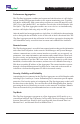
iTap 10 GigaBit Port Aggregator Chapter 1 Introduction Thank you for purchasing the latest innovation in Tap technology, the iTap 10 GigaBit Port Aggregator (iTap Port Aggregator). This device provides ultra‑efficient access to critical 10 Gigabit full-duplex links using only one NIC on each monitoring tool, and supports two tools simultaneously.
iTap 10 GigaBit Port Aggregator Performance Aggregation The iTap Port Aggregator combines and regenerates both directions of a full‑duplex stream, sending all aggregated traffic to two separate monitoring ports. Typically, full-duplex monitoring with a network tap requires two network interface cards (NICs) (or a dual channel NIC), one interface for each side of the full-duplex link.
iTap 10 GigaBit Port Aggregator User-defined Maximum Packet Size The user can set a maximum packet size of 64 to 12,000 bytes for each network port. If any oversized packets are received (the packet length exceeds the programmed value), they are counted and discarded. This function enables the iTap Port Aggregator to pass jumbo packets, but discard packets that are oversized as defined by the user.
iTap 10 GigaBit Port Aggregator CRC Sanitizing The iTap Port Aggregator can be set to drop packets from the monitoring data stream if they are received with CRC errors. This function can clean up the data being sent to monitoring tools, or it can be left off so the monitoring tool can see the packets that have CRC errors. In either case, packets received with CRC errors are counted and reported in the Port Statistics.
iTap 10 GigaBit Port Aggregator Ease of Use • Display alternately shows link utilization, the peak utilization, and the time the peak utilization occurred, for all four ports • LED indicators show redundant power, link status, Tap or Aggregation mode, and utilization alarms • XFP monitor ports provide increased flexibility • All necessary network and monitor cables are included • Optional 19-inch rack frame holds up to two iTap Port Aggregators • Compatible with all major manufacturers’ monitoring devices,
iTap 10 GigaBit Port Aggregator Chapter 2 Installing the iTap Port Aggregator This chapter describes how to install the iTap 10 GigaBit Port Aggregator.
iTap 10 GigaBit Port Aggregator Unpack and Inspect the iTap Port Aggregator Unpack the iTap Port Aggregator and check for damaged or missing parts.
iTap 10 GigaBit Port Aggregator Rack Mount the iTap Port Aggregator (optional) The iTap is designed for rack mounting in a two-slot, 19-inch panel. The mounting panel occupies one rack unit (1U). To rack mount the iTap Port Aggregator: 1. Attach the two-slot panel to your rack using the attached thumbscrews. 2. Slide the iTap into one of the slots and secure with the attached thumbscrews. 3. Make sure that the rack is properly grounded. The iTap can also be placed on a surface using the supplied pads.
iTap 10 GigaBit Port Aggregator Connect the CLI Interface All configuration options, status, and statistics can be accessed using the device's Command Line Interface (CLI). To use the CLI, connect a DB9 cable from the RS232 port on the back of the iTap to your computer. Your computer needs to have terminal emulation software such as HyperTerminal to access the iTap CLI over the RS232 cable. To connect the CLI: 1.
iTap 10 GigaBit Port Aggregator 3. The Net Optics CLI banner and login prompt appear in the Terminal Emulation software (see following figure). Enter the username at the login prompt. The default username is netoptics. ************************************* * Net Optics Command Line Interface * ************************************* login: netoptics password: Figure 4: CLI login prompt 4. Enter the password. The default password is netoptics. The "NetOptics:" prompt is displayed.
iTap 10 GigaBit Port Aggregator Configure the iTap Port Aggregator using the CLI You should be logged into the iTap Port Aggregator CLI. The factory-set default values for this iTap Port Aggregator are: Username: netoptics Password: netoptics IP Address: 192.168.1.2 Netmask: 255.0.0.
iTap 10 GigaBit Port Aggregator For security reasons, some parameters can only be set with the CLI. A complete list of CLI commands can be viewed by typing Help at the CLI prompt. It is also provided in Appendix B.
iTap 10 GigaBit Port Aggregator Assign a New iTap Port Aggregator IP Address Be sure that you have the correct new IP address for the iTap Port Aggregator before you change the IP address value from the default 192.168.1.2. To assign a new IP address to the iTap Port Aggregator: 1. Type set ip . 2. Press Enter. Example: Enter set ip 192.168.1.3 to set the iTap Port Aggregator IP address to 192.168.1.3. Web Manager and System Manager can access the device at this address.
iTap 10 GigaBit Port Aggregator View Current Settings To view the current settings: • Enter show set 1 and show set 2. The CLI displays the current settings; it will be similar to the example shown on the following page. NetOptics: show set 1 Model: System Time: IP Address: Netmask: Manager: Gateway: Port 1 Enable: Port 2 Enable: Display: Management Port: 10G 62.5um SR Inline 05/08/2008 11:29:42 192.168.1.2 255.0.0.0 192.168.0.1 10.0.0.
iTap 10 GigaBit Port Aggregator Using the CLI Help Command To view CLI help information: 1. Enter Help at the "NetOptics:" prompt. The list of help topics is displayed. NetOptics: help ************************************* * Net Optics Command Line Interface * ************************************* Usage: "help " : set - Configure various options. reset - Reset options. show - Show current configurations and status. echo - Turn on or off echoing of characters. help - This help screen.
iTap 10 GigaBit Port Aggregator Connect the iTap Port Aggregator to the Network To connect the iTap to the network: 1. Connect Network Port A to the appropriate network device using the cables supplied with your iTap. 2 1 1 AGG. B 2 A 1 RESET B A LINK www.netoptics.
iTap 10 GigaBit Port Aggregator Connect the Management Port to the Network To use the remote interfaces you must connect the Management Port on the back of the unit to the network. You may wish to connect the Management Port on a dedicated management VLAN for increased security. To connect the Management Port: 1. Connect a CAT5 or CAT5e cable to the Management Port as shown in the following figure. RS232 Management Port To network switch or hub Figure 9: Connecting the Management Port 2.
iTap 10 GigaBit Port Aggregator Turn the Management Port Off and On Check that the Management Port is functional by typing the iTap Port Aggregator IP address in a Web browser. Net Optics Web Manager should display. If it does not, check the Management Port cable connections and use the following procedure to make sure the Management Port is ON. To turn the Management Port off and on: 1. Enter show set 1 to view the current setting. Management Port should be ON.
iTap 10 GigaBit Port Aggregator Connect a Monitoring Device to the Port Aggregator The iTap Port Aggregator is delivered with two monitor cables for connecting to monitoring tools. To connect the cables to the monitoring devices: 1. Connect Monitor Port 1 to the appropriate monitoring device using the cables supplied with your unit 2. Connect Monitor Port 2 to the appropriate monitoring device using the cables supplied with your unit 2 1 1 AGG. B 2 A 1 RESET B A LINK www.netoptics.
iTap 10 GigaBit Port Aggregator Check the Installation You have connected the iTap Port Aggregator to the network, to the monitoring device, and to power. It should now be functioning correctly. Check the status of the following: • Check that at least one power LED is illuminated. • Check the link status LEDs located on the front panel to verify that the links are connected. • Check the display for utilization and peak information.
iTap 10 GigaBit Port Aggregator Chapter 3 Front Panel This chapter describes how to interpret and work with the front panel features of the iTap Port Aggregator. The following topics are covered: • Display • LED indicators • Reset Button Reset Utilization Alarms Mode 2 1 1 AGG. B 2 A 1 RESET B A LINK TM Mode TAP 2 Network A B 1 2 Port Aggregator 10 GigaBit LASER CAUTION! OUT www.netoptics.
iTap 10 GigaBit Port Aggregator Display The front panel of the iTap provides port traffic information on a 2x16 character LCD display. After a boot up message, the display scrolls through the following four screens. • Two screens show the Network and Monitor Port current and peak utilizations, and are displayed for 10 seconds each. • The other two screens show the times of the peak utilizations, and are displayed for 5 seconds each.
iTap 10 GigaBit Port Aggregator Utilization Alarm LEDs Four LEDs indicate that utilization levels have exceeded the threshold. Each LED is the alarm for one port. For Network Ports, utilization is monitored on incoming traffic; for Monitor Ports, the outgoing traffic is monitored. When a Utilization Alarm LED is illuminated, it indicates that the threshold level was exceeded for that port since the last reset. The LEDs remain illuminated until they are reset using the reset button or remote interfaces.
iTap 10 GigaBit Port Aggregator Chapter 4 Using Web Manager This chapter describes how to monitor and control individual iTap Port Aggregators using Net Optics Web Manager software. The iTap Port Aggregator has built-in support for remote control from any computer with an Internet browser and access to the iTap’s IP address. Web Manager is a browser-based interface that enables you to change settings, view status, and retrieve data remotely. Web Manager supports all common browsers.
iTap 10 GigaBit Port Aggregator Figure 12: Web Manager for the iTap 10 GigaBit Port Aggregator 28
iTap 10 GigaBit Port Aggregator The tables in the following sections explain the fields in Web Manager. To save any changes to the iTap, click Submit Changes at the bottom of the page. View System Status Web Manager displays status information about the iTap Port Aggregator and its ports. System Status UP indicates the iTap is functioning correctly. If the System Status is DOWN, there is an internal error. For more information, contact Net Optics Technical Support.
iTap 10 GigaBit Port Aggregator If a link is down, check the cables and power supplies, and make sure the device on the other end of the link is functioning properly. View iTap Traffic Statistics Web Manager displays iTap traffic statistics for both Network Ports and both Monitor Ports. The statistics for the Network Ports apply to traffic received into the port. The statistics for the Monitor Ports apply to traffic transmitted out of the port.
iTap 10 GigaBit Port Aggregator Change iTap Port Aggregator System Configuration Web Manager has both read-only and writable fields. Use the writable fields in the Aggregator System Configuration section to set configuration parameters. To change a parameter, type the new value into the field or select it from the list, and then click Submit Changes at the bottom of the page to send the changes to the iTap Port Aggregator device.
iTap 10 GigaBit Port Aggregator The following table describes each available configuration option. Field Name Description IP Address IP address of the iTap. The default IP address is 192.168.1.2. Change the IP address by typing a new IP address in the text box. This is the address for Web Manager and System Manager to communicate with the device. Net Mask Displays current Net Mask of the iTap. The default Net Mask is 255.0.0.0. Change the IP address by typing a new Net Mask in the text box.
iTap 10 GigaBit Port Aggregator Field Name Description Reset Port 1 Statistics Select Yes to zero all counters for Port 1. Reset Port 2 Statistics Select Yes to zero all counters for Port 2. Port 1 Mode Select AGG to set Port 1 to aggregation mode. Select TAP to set Port 1 to Tap mode. Note: Both Monitor Ports must always be set to the same mode or the device behavior will be undefined. Port 2 Mode Select AGG to set Port 2 to aggregation mode. Select TAP to set Port 2 to Tap mode.
iTap 10 GigaBit Port Aggregator Chapter 5 Using System Manager This chapter describes how to install and use Net Optics' System Manager, a software tool that provides a central console to manage all the iTap-enabled Net Optics devices on your network. Using System Manager, you can change settings, view status, and retrieve data remotely from multiple Net Optics iTap devices. System Manager is compatible with computers and workstations running Windows XP, Windows 2000, and Windows 98.
iTap 10 GigaBit Port Aggregator Install System Manager The installation executable file for System Manager is on the CD included with the iTap device. To install System Manger: 1. Load the System Manager software CD in the computer's CD drive. The License Agreement dialog box appears. (If the License Agreement dialog box does not appear, locate Setup.exe on the CD and double click it.) Figure 16: Net Optics System Manager License Agreement 2.
iTap 10 GigaBit Port Aggregator 7. To continue the installation, click Next. The Progress dialog box appears. When the installation is complete, the Installation Complete dialog box appears. 8. Click Close. System Manager is now installed on your computer and a Net Optics shortcut icon appears on your desktop. Explore System Manager This section describes the features and functions of System Manager.
iTap 10 GigaBit Port Aggregator Figure 17: Initial System Manager window The left side of the window is the System Frame. It displays iTap devices and iTap Groups as you add them to the system. The right side is the Information Frame. It displays Configuration and Status information for individual iTap devices. Tip!______________________________________________________________________ To use pop-up menu shortcuts, click your right mouse button in the System Frame.
iTap 10 GigaBit Port Aggregator Using the Toolbar The following figure shows the System Manager toolbar. Figure 18: System Manager Toolbar The table below describes the icons found on the toolbar.
iTap 10 GigaBit Port Aggregator Delete a System Manager Group You can delete groups you have created. However, be aware that all devices in that group will also be deleted from System Manager. To delete a Group: 1. Right-click on the group bar of the group you want to delete. 2. Select Delete from the menu. The group and all associated devices are deleted from System Manager.
iTap 10 GigaBit Port Aggregator 4. Enter the IP address of the iTap device in the IP Address text box. Be certain that the IP address is unique on the network. 5. Enter any relevant information about the iTap device in the Notes text box. 6. Check your settings and click Create. The device appears in the System Manger system frame. Figure 21: Net Optics System Manager with a device The indicator to the right of the iTap device picture blinks green when System Manager is communicating with the iTap device.
iTap 10 GigaBit Port Aggregator Modify an iTap device Name or IP Address You can change the iTap device name, IP address and Notes from the Modify iTap dialog box. To modify the iTap device configuration: 1. Select the device you want to modify by clicking its icon in the System Frame. 2. Click Modify in the toolbar. The Modify Node dialog box appears. Figure 22: Modify iTap dialog box 3. Make the desired changes and click Save Change.
iTap 10 GigaBit Port Aggregator Delete an iTap device from System Manager When you remove an iTap device from your network, you should delete the device from System Manager. Otherwise, System Manager will continue to poll the iTap device’s IP address for data, wasting system resources. To delete an iTap device from System Manager: 1. Select the device you want to delete by clicking its icon in the System Frame. 2. Click Delete in the toolbar. A confirmation dialog box appears. 3.
iTap 10 GigaBit Port Aggregator Figure 23: iTap Port Aggregator Status Tab TIP!______________________________________________________________________ Fields that have been updated since the last refresh appear with a circle and arrow to the left of the value field. For example, see Power Supply 1 Status in Figure 23.
iTap 10 GigaBit Port Aggregator The following table describes the status fields. Field Name Value Description System Status UP/DOWN DOWN indicates an internal error; call Net Optics Customer Service for assistance System Model 10G 62.
iTap 10 GigaBit Port Aggregator Figure 24: iTap Port Aggregator Configure tab 3. Click on the value corresponding to the parameter you wish to configure. 4. Select an option from the drop-down list, or enter a new value from your keyboard, followed by the Enter key. 5. The new configuration parameters take effect the next time System Manager polls the iTap Port Aggregator.
iTap 10 GigaBit Port Aggregator The following table describes each available configuration option. Field Name Description IP Address IP address of the iTap. The default IP address is 192.168.1.2. Change the IP address by typing a new IP address in the text box. This is the address for Web Manager and System Manager to communicate with the device. Net Mask Displays current Net Mask of the iTap device. The default Net Mask is 255.0.0.0. Change the IP address by typing a new Net Mask in the text box.
iTap 10 GigaBit Port Aggregator Field Name Description Reset Port 1 Statistics Select Yes to zero all counters for Port 1. Reset Port 2 Statistics Select Yes to zero all counters for Port 2. Current Date & Time The current system time. This clock is used to record the time of traffic utilization peaks. Port 1 Mode Select AGG to set Port 1 to aggregation mode. Select TAP to set Port 1 to Tap mode. Note: Both Monitor Ports must always be set to the same mode or the device behavior will be undefined.
iTap 10 GigaBit Port Aggregator Appendix A Specifications and Models Specifications Electrical Power Supply Input 100-240VAC, 0.5A, 47-63Hz Power Supply Output 12V, 5A Environmental Operating Temperature 0˚C to 40˚C Storage Temperature -10˚C to 70˚C Relative Humidity 10% min, 95% max, non-condensing Mechanical Dimensions 1.375” high x 11” deep x 8.5” wide Weight 8 lbs (3.6 kg) maximum, bare unit 10 lbs (4.
iTap 10 GigaBit Port Aggregator Optical Interface SR Fiber Types Corning Multimode 62.5/125μm, wavelength 850nm Split Ratio Network Port Insertion Loss 50/50 ~ 3.3 dB Corning Multimode 50/125μm, wavelength 850nm Split Ratio Network Port Insertion Loss 50/50 ~ 3.3 dB LR Fiber Type Corning Singlemode 8.5/125μm, wavelength 1310nm Split Ratio Network Port Insertion Loss 50/50 ~ 3.3 dB ER Fiber Type Corning Singlemode 8.5/125μm, wavelength 1550nm Split Ratio Network Port Insertion Loss 50/50 ~ 3.
iTap 10 GigaBit Port Aggregator Software Command Line Interface Any terminal emulation software Net Optics Web Manager Any browser Net Optics System Manager Windows XP, Windows 2000, Windows 98 Certifications Fully RoHS compliant Models and Part Numbers Part Number Description IPA-SR5-XFP 10 Gig SR Multimode, 62.5µm, In-Line IPA-50SR5-XFP 10 Gig SR Multimode, 50µm, In-Line IPA-LR5-XFP 10 Gig LR Singlemode, 8.5µm, In-Line IPA-ER5-XFP 10 Gig ER Singlemode, 8.
iTap 10 GigaBit Port Aggregator Appendix B Command Line Interface Tip!______________________________________________________________________ The command line interface (CLI) is not case sensitive.
iTap 10 GigaBit Port Aggregator Command Sub-Command Syntax Description Set (continued) Username set username Where is the authorized user's name, 32 characters or less Password set password Where is the authorized user's password, 32 characters or less Mgtport set mgtport Where is 1 = Managment Port on 2 = Management Port off (other values not applicable) Enable Port set enable port Where is 1
iTap 10 GigaBit Port Aggregator Command Sub-Command Syntax Description Set (continued) Dropbad Port set dropbad port Where is A or B and is 1 = Drop packets with CRC errors 2 = Pass packets with CRC errors (other values not applicable) Note: Applies to CRC errors as the packet is received at the Monitor Port Psize Port set psize port Where is A or B and is 64 to 12000 (other values not applicable) Note: Sets th
iTap 10 GigaBit Port Aggregator Command Sub-Command Syntax Description Reset Peak Port reset peak Where is A, B, 1 or 2 Statistics Port reset statistics port Where is A, B, 1 or 2 Default reset default Resets configuration back to factory defaults: Port 1 & 2 Enable = ON Management Port = ON Port Modes = AGG Max Packet Sizes = 1518 Port Slice Sizes = 64 All Set 2 features = OFF Set show set Where is 1 = Show page 1 2 = Show page
iTap 10 GigaBit Port Aggregator Limitations on Warranty and Liability Net Optics offers a limited warranty for all its products. IN NO EVENT SHALL NET OPTICS, INC. BE LIABLE FOR ANY DAMAGES INCURRED BY THE USE OF THE PRODUCTS (INCLUDING BOTH HARDWARE AND SOFTWARE) DESCRIBED IN THIS MANUAL, OR BY ANY DEFECT OR INACCURACY IN THIS MANUAL ITSELF.
iTap 10 GigaBit Port Aggregator Notes: 59
www.netoptics.com © 2010 by Net Optics, Inc. All Rights Reserved.