Installation Guide for 8x1 Regeneration TapsTM 10G, 1G, and 10/100/1000 Speeds RG-800 Series Regen Tap A B Network A Network B Network A Network B SX 10 Gigabit 1 Gigabit Doc.
8x1 Regeneration Taps PLEASE READ THESE LEGAL NOTICES CAREFULLY. By using a Net Optics Regeneration Tap you agree to the terms and conditions of usage set forth by Net Optics, Inc. No licenses, express or implied, are granted with respect to any of the technology described in this manual. Net Optics retains all intellectual property rights associated with the technology described in this manual. This manual is intended to assist with installing Net Optics products into your network.
8x1 Regeneration Taps Contents Introduction. . . . . . . . . . . . . . . . . . . . . . . . . . . . . . . . . . . . . . . . . . . . . . . . . . . . . . 1 Key Features. . . . . . . . . . . . . . . . . . . . . . . . . . . . . . . . . . . . . . . . . . . . . . . . . . . . . 2 About This Guide. . . . . . . . . . . . . . . . . . . . . . . . . . . . . . . . . . . . . . . . . . . . . . . . . 3 Unpacking and Inspection. . . . . . . . . . . . . . . . . . . . . . . . . . . . . . . . . . . . . . . . . . .
8x1 Regeneration Taps Introduction Net Optics 8x1 Regeneration Taps solve the key physical layer challenges of multi-device network monitoring. For a better picture of network health, these Taps connect up to eight different network management and security devices at any single network location or two switch Span ports.
8x1 Regeneration Taps Inline or Span Ports Models are available for either inline or Span deployments. Inline models tap one link and create eight copies of the traffic traveling in one direction on the link, plus eight copies of the traffic traveling in the other direction. A monitoring tool with two NICs has visibility of the full duplex traffic at full link bandwidth.
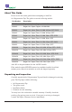
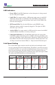
8x1 Regeneration Taps About This Guide Please review this entire guide before attempting to install an 8x1 Regeneration Tap. The guide covers the following models: Part Number Description RG-820 Regen, 8x1, Inline, Copper, 10/100/1000 RG-825 Regen, 8x1, Span, Copper, 10/100/1000 RG-830 Regen, 8x1, Inline, Fiber, 1G, MM, 62.5µm, SFP, 50:50 RG-835 Regen, 8x1, Span, Fiber, 1G, MM, 62.
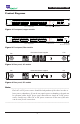
8x1 Regeneration Taps Product Diagrams Regen Tap A B Full duplex 1000 100 10 Power LEDs Network A Mode LEDs 16 RJ45 Monitor Ports for 8 x 1 Regeneration Network B Push to change mode 2 RJ45 Network Ports Mode Change Button (recessed) Figure 1: Front panel, copper models Regen Tap A B Network A Network A Network B SX Network B 10 Gigabit 1 Gigabit Power LEDs Link & Speed LEDs for Network Ports 16 SFP Monitor Ports for 8 x 1 Regeneration LC Network Ports Bubble Label SX, LX, SR, LR, 50
x1 Regeneration Taps LED Indicators • Power LEDs: Each LED illuminates to show that power is being sourced by one of the power supples. • Link LEDs: For copper models, a LED on the right corner of each RJ45 illuminates when a link is established. The Link LEDs for fiber network ports are located in the top two positions in the stack of four LEDs to the left of the network ports. • SFP Present LEDs: The left side LED above each SFP/SFP+ cage illuminates when a module is properly plugged in.
",' 8x1 Regeneration Taps Warnings on Product WARNING: Warranty void if removed Two of the labels illustrated above cover screws on the chassis top cover near the front corners. They prevent you from taking the cover off without voiding your warranty. You should not take the cover off because there are no user‑serviceable parts inside, and there is a danger of electrical shock. Symbols on Product Indicates WEEE compliance +4cb$F($23d6 O@
8x1 Regeneration Taps Connecting Power Use the following procedures to safely connect AC or DC power to the unit. Caution:_ ____________________________________________________________ For AC models, use the AC power cords supplied with the product. If you use other AC power cords, they should have a wire gauge of at least 20 and a 230VAC 1A rating. Be sure to use a three-prong cords and connect them to sockets with good earth grounds. For DC models, you must supply your own power cables.
8x1 Regeneration Taps To connect DC input power on DC models: 1. If you have not already done so, unpack the Regeneration Tap and verify that you have appropriate DC power cables. You also need a Phillips screwdriver to complete the installation. 2. If present, remove the protective covers from the DC power terminal blocks. 3. Connect an earth ground lead to the terminal labeled with the ground symbol ( ), which is the left-most terminal, on both DC power terminal blocks on the rear of the chassis.
8x1 Regeneration Taps Connecting to the Network 1. Connect Network Port A to the appropriate switch Network or Span port using a an appropriate cable. 2. Connect Network Port B to the appropriate switch Network or Span port using an appropriate cable. 3. Check the Link and Activity LEDs to verify that the Regeneration Tap is receiving traffic into the Network ports. For inline models, verify that traffic is passing between the devices on both sides of the Regeneration Tap.
8x1 Regeneration Taps Connecting to the Monitoring Devices 1. If you have a fiber model, install the appropriate SFP or SFP+ transceiver modules in the Monitor ports. (You need to install modules only in ports to which you will be connecting monitoring tools). Push each module in until you hear a click and see the SFP Present LED above the port illuminate. 2. Connect any Monitor A port to the appropriate monitoring device using an appropriate cable.
8x1 Regeneration Taps Specifications Environmental Temperature: 0ºC to 40ºC (Operating), -10ºC to 70ºC (Storage) Relative Humidity: 10% min, 95% max, non-condensing Redundant Power Supplies, each Input: 100-240VAC, 0.5A, 47-63Hz DC Input: -48VDC nominal, -36 to -72VDC, 1A Power Consumption: 50W Mechanical Dimensions: 1.
8x1 Regeneration Taps Limitations on Warranty and Liability Net Optics offers a limited warranty for all its products. IN NO EVENT SHALL NET OPTICS, INC. BE LIABLE FOR ANY DAMAGES INCURRED BY THE USE OF THE PRODUCTS (INCLUDING BOTH HARDWARE AND SOFTWARE) DESCRIBED IN THIS MANUAL, OR BY ANY DEFECT OR INACCURACY IN THIS MANUAL ITSELF.
www.netoptics.com © 2010 by Net Optics, Inc. All Rights Reserved.