SERVICE MA NUA L CITIZ COFFEE MA CHINES Citiz EF 483/484 Citiz & milk EF 485/486 Citiz & Co EF 487/488 Version 1.
CONTENTS 1 General Safety Notes ........................................................................................ 6 2 Model overview ................................................................................................... 7 2.1 Model range ....................................................................................................... 7 2.2 Core unit versions .............................................................................................. 8 3 3.
6 Maintenance ...................................................................................................... 38 6.1 Daily maintenance and cleaning ...................................................................... 38 6.1.1 Before first coffee or at the start of day .................................................. 38 6.1.2 After last coffee or at the end of day....................................................... 39 6.1.3 Milk frother of model Citiz & milk .................................
9 Function tests ................................................................................................. 130 9.1 Safety instructions.......................................................................................... 130 9.2 Required equipment....................................................................................... 130 9.2.1 Overview ............................................................................................... 130 9.2.2 Pressure adapter ..................
PREFACE The purpose of this service manual is to provide the service personnel with all necessary information with regards to correct handling, maintenance and repair of the Citiz coffee machine types EF 483/484, EF 485/486 and EF 487/488. This manual should be used by the technicians as a valuable aid to guarantee the permanent readiness for use of the machines. In order to take full advantage of all the functions, it is absolutely necessary to follow the instructions in this manual.
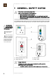
GENERAL SAFETY NOTES 1 GENERA L SA FETY NOTES Risk of fatal electrical shock and fire! Mains voltage inside the coffee machine. • • • Unplug appliance before cleaning. Never clean wet or immerse plug, cord or appliance in any fluid. Disconnect the mains plug before disassembly the appliance must be free of voltage. As an additional safety measure, the use of a residual current device (RCD), also called the ground fault circuit interrupter (GFCI), in the repair centre is highly recommended.
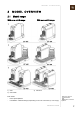
MODEL OVERVIEW 2 2.1 MODEL OVERVIEW Model range With core unit Drange: 1) Citiz 2) Citiz & milk With core unit Crange: 3) Citiz & Co Each model has a special platform is available in 2 different designs, depending on the core unit version (C or Drange). A core unit is the actual coffee machine, mounted on a platform.
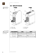
MODEL OVERVIEW 2.2 This comparison helps to identify the core unit version. Core unit versions Drange 1) Coffee outlet 2) Closing handle There are additional differences between the 2 versions (cov ers, wiring etc.) not men tioned in the table.
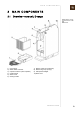
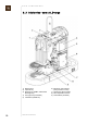
MAIN COMPONENTS 3 MA IN COMPONENTS 3.1 Overview core unit, Drange For platform compo nents refer to model overview.
MAIN COMPONENTS 3.1.
MAIN COMPONENTS 3.
MAIN COMPONENTS 3.2.
MAIN COMPONENTS 3.3 Overview model Citiz This model is pictured with a Crange core unit. 1) 2) 3) 4) 5) Drip grid Drip tray Core unit (e.g. Crange) Water tank cover Water tank 6) 7) 8) 9) Water tank connector Power cord ON/OFF switch (mains switch) Platform This is the basic model with the smallest platform (9). The drip grid (1) exists in 2 versions, matches with the cup holder of the core unit version (e.g. circular recesses).
MAIN COMPONENTS 3.4 Overview model Citiz & milk This model is pictured with a Crange core unit. 1) 2) 3) 4) 5) 6) 7) 8) The core units of model Citiz and Citiz & milk are not com patible due to different electronic control boards. 14 Drip grid Drip tray Platform Storage places for whisks Core unit (e.g.
MAIN COMPONENTS 3.4.1 Overview milk frother AERO3 The milk frother AERO3 is part of the standard equipment of the model Citiz & milk. 1) 2) 3) 4) 5) Lid Seal Jug Power plug Start button (red/blue backlighted) 6) Indication of 2 max. milk levels (120 ml/240 ml) 7) Mixer for hot milk 8) Spring whisk for milk foam The inside of the jug (3) has level marks (6), is surfacecoated for easy cleaning.
MAIN COMPONENTS 3.5 Overview model Citiz & Co This model is pictured with a Crange core unit. 1) 2) 3) 4) Drip tray Drip grid ON/OFF switch (mains switch) Power cord 5) 6) 7) 8) Core units (e.g. 2 x Crange) Water tank Water tank cover Platform The drip grid (1) exists in 2 versions, matches with the cup holder of the core unit version (e.g. circular recesses).
MAIN COMPONENTS 3.6 Fluid System 3.6.1 Water circuit diagram of core unit (all Citiz versions) 1) 2) 3) 4) 5) Water tank Flow meter Pump Self priming device Thermoblock 6) 7) 8) 9) Mini brewing unit (MBU) Capsule container Waste water container Drip tray Legend: Fresh cold water Fresh hot water Coffee Waste/drip water The self priming device (4) allows the pump to suck water when it is filled with air (new machine, empty water tank etc.
MAIN COMPONENTS 3.6.
MAIN COMPONENTS 3.6.
TECHNICAL DATA 4 4.1 The type plate can be found at the bottom of the coffee machine’s platform. TECHNICAL DATA Rating plates 4.1.1 Examples of brand specific rating plates Nespresso, EUversion This overview shows examples of various brands and is subject to alterations.
TECHNICAL DATA DeLonghi, EUversion EF483 Citiz D110 Limousine black/DeLonghi EN165.B EF483 Citiz D110 60's White/DeLonghi EN165.CW EF485 Citiz & milk D120 Limousine black/DeLonghi EN265.BAE EF487 Citiz & Co. D130 Limousine black/DeLonghi EN325.B Koenig, CHversion EF483 Citiz D110 Limousine black/Koenig Citiz EF483 Citiz D110 60's White/Koenig Citiz EF485 Citiz & milk D120 Limousine black/Koenig Citiz & milk EF487 Citiz & Co. D130 Limousine black/Koenig Citiz & Co.
TECHNICAL DATA Krups, EUversion EF484 CitiZ XN700510 grey EF484 CitiZ XN700610 red EF486 CitiZ & milk XN710610 red EF488 CitiZ & Co XN750510 grey Magimix, EUversion 22 EF483 Citiz M190 Ref 11290 black EF483 Citiz M190 Ref 11291 cream EF485 Citiz M190 Milk Ref 11300 black EF487 Citiz M190 Duo Ref 11305 black Citiz service manual
TECHNICAL DATA Turmix, ATversion EF484 Citiz C110 fire engine red/ Turmix TX 170 Citiz EF484 Citiz C110 steel grey/Turmix TX 170 Citiz EF486 Citiz & milk C120 fire engine red/ Turmix TX 270 Citiz & milk EF488 Citiz & Co. C130 steel grey/ Turmix TX 370 Citiz & Co. 4.1.
TECHNICAL DATA Decoding the alphanumeric serial number By decoding the date of production and machine type, the coffee machine can be identified exactly. Example: Checksum (if available) Color version Type of mains plug Mains voltage Distributing partner Incremental number per production day Manufacturing plant Manufacturer designation of the machine type (EF 484) 08312 ... Date of production (08 = year 2008, 312 = 312 day of the year) 4.1.
TECHNICAL DATA 4.2 Summary of technical data 4.2.1 Technical data of coffee machines Mains voltage ranges Mains voltage for Citiz Europe, RU, AU, CN, KR, SG, HK, ME, ZA, IL, BR, AR........... 220240 V / 5060 Hz Technical data are valid for all Citiz mod els unless explicitly stated otherwise. USA, Canada, BR, MX .............................................................. 120127 V / 5060 Hz Japan ..............................................................................................
TECHNICAL DATA 1 large cup (110 ml*) Citiz ...................................................................................................... approx. 8.7 Wh Citiz & milk ........................................................................................... approx. 8.7 Wh Citiz & Co (both heads) ...................................................................... approx. 14.8 Wh * Default setting Standby operation (in 1 hour) Citiz ........................................................
TECHNICAL DATA 4.2.2 Technical data of milk frother (model Citiz & milk) Mains voltage Europe ........................................................................................ 220240 V / 5060 Hz USA/Canada ................................................................................ 120127 V / 5060 Hz The milk frother is available in 2 different models, depending on above mains voltage ranges, has to match the mains voltage range of the associated coffee machine.
TECHNICAL DATA Performance data Whisk speed......................................................................................... 2’0002’700 rpm Preparation times (with full, semiskimmed or skimmed milk at 8 °10 °C fridge temperature) Hot milk froth (120 ml) .....................................................................................5080 sec Cold milk froth (120 ml) ...................................................................................6080 sec Hot milk (240 ml) ...............
TECHNICAL DATA 4.2.4 Dimensions and weight model Citiz & milk The overall dimen sions are the same for both core unit ver sions (C and Drange). Dimensions in mm Dimensions (width x height x length) ............................................ 237 x 277 x 372 mm Weight (without water, milk frother included) ...........................................approx. 4.6 kg 4.2.5 Dimensions and weight milk frother Dimensions of jug cpl. (diameter x height) ................................................
TECHNICAL DATA 4.2.6 Dimensions and weight model Citiz & Co The overall dimen sions are the same for both core unit ver sions (C and Drange). Dimensions in mm. Dimensions (width x height x length)............................................. 326 x 281 x 286 mm Weight (without water).................................................................................approx.
OPERATION 5 OPERATION 5.1 General information For an overview of operational controls see “Main Components” on page 9. For basic operation of the machine such as preparing a coffee and other related infor mation, refer to the user manual. To simplify matters, the model Citiz with core unit Crange is used to exemplify throughout this chapter. 5.2 Status indication 5.2.
OPERATION Machine status etc. Volume brewing small cup Volume brewing big cup Descaling ready Descaling pump on (descal) Descaling pump off (descal) 32 " Small cup" button " Large cup" button LED signal Blinking 1 Hz, 0.5 s on, 0.5 s off (same as brewing small cup) Blinking 1 Hz, 0.5 s on, 0.5 s off (same as brewing big cup) Blinking 2 Hz, 0.25 s on, 0.25 s off Blinking 2 Hz, 0.25 s on, 0.25 s off (same as descaling ready mode) Blinking 2 Hz, 0.25 s on, 0.
OPERATION Machine status etc. " Small cup" button " Large cup" button LED signal Blinking 0.5 Hz, 1 s on, 1 s off alternately 3 times Power save deactivation (only for model Citiz & Co) 5.2.2 Status indication of milk frother AERO3 The operating button with red/blue backlight shows the status of the milk frother according to the following table: Machine status etc.
OPERATION 5.3 Machine modes 5.3.
OPERATION Machine mode Actions Exit mode Start pump Stop pump after 10 s 3) Heat up thermo block to 105 °C Switch off machine (100% power) 4) Switch off ther moblock 5) Go to standby mode 1) Switch off machine • Reset the 2) Press and hold programmed large large coffee button and small coffee 3) Switch on machine volumes to factory setting proceeds with self test • Indicate the resetting mode automatically mode for 3 s Factory settings: • small cup .... 40 ml • large cup ...
OPERATION 5.4 Program/reset fill up level Each coffee button can be programmed with a coffee volume for an individual cup size. The procedure for programming/resetting is the same for both coffee buttons. 5.4.1 Programming the fill up level Programmable volume range .......................................................................... 10750 ml Each new program ming cycle starts with the min. volume (10 ml after 3 sec), regard less of a preprogrammed coffee volume.
OPERATION 5.5 Empty water system After every operation, some water remains in the coffee machine. Therefore the water system must be emptied if the coffee machine will not be used for a long time as antifreeze measure for repairs and shipment. 1) Switch off coffee machine. 2) Remove water tank. 3) Place a beaker under the coffee out let. Model Citiz & Co: Only one core unit should be emptied at the same time (danger of mains supply overload).
MAINTENANCE 6 MA INTENA NCE 6.1 Daily maintenance and cleaning 6.1.1 Before first coffee or at the start of day The Citiz model is shown as example. Maintain and clean other models accordingly. 38 1) Fill water tank with fresh potable water. 2) Insert water tank. 3) For model Citiz & milk: Attach whisk to milk frother. Place milk frother on base plate connector. 4) Switch machine on. After a longer period of non use: 5) Place a container under coffee outlet.
MAINTENANCE 6.1.2 After last coffee or at the end of day Risk of fatal electrical shock and fire! Never clean wet or immerse plug, cord or appliance in any fluid. Unplug appliance and let it cool down to avoid burns. Platform and drip tray surfaces are not abrasionproof. Never use brushes and/or cleaning agents that con tain aggressive or chemical components resp. sol vents. Do not put any part in a dishwasher.
MAINTENANCE 6.1.3 Milk frother of model Citiz & milk Risk of damage! The inside of the jug is coated for easy cleaning. Never use brushes and/or cleaning agents that contain abrasive or aggressive, chemical components resp. solvents. Do not put any part in a dishwasher. Use only a damp cloth and a mild cleaning agent if necessary. 1) Remove milk frother from platform. 2) Remove lid and dismantle whisk. 3) Remove seal from lid. 4) Rinse and clean milk frother together with whisk or mixer, lid and seal.
MAINTENANCE 6.2 Descaling Only use Nespresso descaler or descaling kit never use vinegar! Descaler can damage casing and contact surfaces. Immediately clean drops of descaling solution. The descaling chart is based on a cup size of 40 ml. fH ... French grade dH ... German grade CaCO3 ... Calcium carbonate Use this chart to inform a customer when to descale the coffee machine depending on local water hardness and average coffee consumption. Double the estimated time interval for model Citiz & Co. 6.2.
MAINTENANCE Observe the safety instructions on the descaler package. Use a container with a capacity of 1 l min. 42 3) Reassemble coffee machine without water tank. 4) Place a container on the cup support. 5) Fill the water tank with 0.1 l decalcifier (1 bag) and 0.5 l water. 6) Insert water tank into the coffee machine. 7) Press both coffee buttons simulta neously for at least 3 sec. 8) The machine is in descaling mode now (both buttons blinking fast).
MAINTENANCE Danger! Hot splashes of descaling solution. Do not open handle dur ing descaling process. 9) Press any button to start pump. Let the entire solution in the tank run through the system. 10) After water tank is empty, pour descal ing solution back into water tank. 11) Place empty container back on cup support. 12) Descale again: press any button and wait until water tank is empty.
MAINTENANCE Danger of injury! Residual descaler may be harmful. Rinse thoroughly to remove any residue. 44 13) Empty container and put it back on cup support. 14) Rinse and clean water tank thoroughly and fill it with fresh potable water. 15) Rinse coffee machine by pressing any button and wait until water tank is empty. 16) Press both coffee buttons simultane ously for at least 3 sec to end descal ing mode. 17) Remove and empty container. 18) Switch off coffee machine.
MAINTENANCE 6.2.2 Descaling procedure for model Citiz & Co 1) Eject capsules or check if capsules are removed. 2) Remove and empty capsule/waste water containers, drip tray and water tank. Observe the safety instructions on the descaler package. 3) Reassemble coffee machine without water tank. 4) Place a container under each coffee outlet. 5) Fill the water tank with 0.2 l decalcifier (2 bags) and 1.0 l water. 6) Insert water tank into the coffee machine.
MAINTENANCE 7) Press both coffee buttons simulta neously for at least 3 sec. on first core unit. 8) Repeat procedure with second core unit. 9) The machine is in descaling mode now (both coffee buttons blinking fast on core units). 10) Press any button on a core unit to start pumps. Let the entire solution in the tank run through the system. 11) After water tank is empty, pour descal ing solution from both containers back into water tank. Danger of injury! Hot splashes of descaling solution.
MAINTENANCE 12) Place empty containers back on cup supports. 13) Descale again: press any button on a core unit and wait until water tank is empty. 14) Empty containers and put them back on cup supports. 15) Rinse and clean water tank thoroughly and fill it with fresh potable water. 16) Rinse coffee machine by pressing any button on first core unit. 17) Repeat procedure on second core unit and wait until water tank is empty.
MAINTENANCE 18) Press both coffee buttons simultane ously for at least 3 sec to end descal ing mode. 19) Repeat procedure on second core unit to end descaling mode. 20) Remove and empty containers. 48 Citiz service manual 21) Switch off coffee machine. 22) Empty and clean capsule/waste water containers and drip tray. 23) Clean coffee machine with a damp cloth if necessary.
TROUBLESHOOTING 7 7.1 TROUBL ESHOOTING Check list for coffee machine (all models) Check Error symptoms Measure / repair work YES replace housing parts if 1.1 Housing parts bro necessary ken or damaged NO continue 1 Check the coffee machine for visi YES replace power cord ble damage 1.2 Power cord dam NO connect power cord of aged machine to the mains and con tinue YES check if the capsule and 2.
TROUBLESHOOTING Check Error symptoms 5.1 No coffee 5 Measure coffee temperature dur ing preparation (see page 136) 5.2 Temperature is too low (below 83°C) 5.3 Temperature too high (over 89 °C) 6.1 Compact brewing unit leaks 6 Check for leakage (see page 133) 6.2 Hose connections and measure flow leak rate (see page 132) 6.3 Rate of flow not in the standard range 7 Descale coffee machine (if necessary) 7.1 Coffee machine is calcified 8 Check water tank 8.
TROUBLESHOOTING 7.2 Check list for milk frother Check Error symptoms Measure / repair work 1.1 Lid/seal broken or damaged 1 Check milk frother and accessory for visible damage 4 Place milk frother on platform con nector. Attach whisk. Switch on coffee machine. Press start button briefly (hot milk preparation). 5 Press start button for at least 2 sec (cold milk prepa ration) 6 Final cleaning (see page 40) YES replace lid/seal NO continue YES replace milk frother in 1.
REPAIRS 8 REPAIRS These repair instructions are based on exploded drawings with position numbers combined with repair and mounting tips, presuppose basic knowledge in repairing Nespresso coffee machines. As a rule, identical components (e.g. pumps, thermoblocks etc.) are presented in detail only once. 8.1 Safety instructions Risk of fatal electrical shock! Mains voltage inside the coffee machine. Disconnect the mains plug before disassembly the coffee machine must be free of voltage.
REPAIRS Screw / screw connection Torque Screw with oval shaped head 50 (+30/0) Ncm 0.5 (+0.3/0) Nm TX 10 screw (4 x) / brewing unit (TMBU) 50 (+30/0) Ncm 0.5 (+0.3/0) Nm TX 10 screw / thermoblock support (central) 150 (+30/0) Ncm 1.5 (+0.3/0) Nm NTC fixation on thermoblock 80100 Ncm 0.81.0 Nm TX 20 screw (2 x) / thermo fuse fixations on ther moblock 150 (+30/0) Ncm 1.5 (+0.
REPAIRS Screw / screw connection Torque TX 20 screw / ground connection (PE) on ther moblock 150 (+30/0) Ncm 1.5 (+0.3/0) Nm Position Designation of spare parts The components in the following illustrations are indexed with position numbers. See separate spare parts list for corresponding spare part numbers. Distinguish between spare parts of the different models and core unit versions.
REPAIRS 8.3 Tools and accessories With the following assortment of tools, all repairs described can be made: 1) Special screwdriver with short oval bit (EFR no. 0004872) 2) Short oval bit only (EFR no. 0004878) 3) Disassembly tool (for side panels etc.) (EFR no.
REPAIRS 8.4 Platform disassembly model Citiz 8.4.1 General disassembly This general disassembly is necessary before the removal/disassembly of a core unit is possible, gives access to the components and wiring of the platform. • 56 Take away all removable parts from platform and core unit cup support (8) with waste water container (6) capsule container (7) drip tray (46) with drip grid (49) water tank (44) with cover (45).
REPAIRS • Loosen 2 screws (41, oval shaped head) at the bottom side of platform. • Use screwdriver to release latches. Start by inserting the srewdriver in the opening for the power cord. The bottom cover (51) is inserted into the platform with both edges of its small end. Only remove bottom cover by swinging up the round end. • Remove bottom cover (51) by swinging it up like shown.
REPAIRS Assembly checkpoints • Check if 2 rubber stoppers are mounted on waste water container (6). • Insert bottom cover (51) with small end into platform at first. Then fold it down and close latches. Take care not to jam any wires at the screw connections.
REPAIRS 8.4.2 Replacing water tank connector The water tank con nector (53) is replaced together with gasket, clamping ring and metal sieve. • Pull off both hoses from water tank connector (53). • Release the 3 latches around the water tank connector one after the other by pressing the top of their hooks outwards with a screwdriver (see detail) and lifting the water tank connector at the same time. • Remove gasket (a) from water tank connector (53).
REPAIRS Assembly checkpoints • Check that gasket is inserted in water tank connector (53) correctly. • During assembly of the water tank connector on the platform, each of its 3 latches has to engage with an audible click. • Mind the different diameters of hoses for the water tank connector. 8.4.3 Replacing mains switch The hoses can remain on the water tank connector. • Remove water tank connector from platform first (see page 59).
REPAIRS Assembly checkpoints • Use marked cable guide to lay wires. • The mains switch holder (54) has a notch: correct fitting position is with mains switch connections next to the platform (see detail). • During assembly of the water tank connector (53) on the platform, each of its 3 latches has to engage with an audible click.
REPAIRS 8.4.4 Replacing power cord The hoses can remain on the water tank connector. • Remove water tank connector from platform first (see page 59). Use a pair of flat pli ers to pull off insulat ing sleeve with recep • Remove insulated faston receptacle of phase wire from mains switch (54). • Disconnect adapter plug of neutral wire (15). The flat receptacle on the ground wire has a special connector latching (see detail). Press down lever at first, then pull off receptacle.
REPAIRS Assembly checkpoints Wiring with threecore power cord: Wiring with twocore power cord: • Use marked cable guides to lay wires. • Check wiring (see "Wiring diagrams model Citiz" on page 118 and following). • During assembly of the water tank connector (53) on the platform, each of its 3 latches has to engage with an audible click.
REPAIRS 8.4.5 Removing core unit Pay attention to the following safety advice before removing the core unit. Danger of insulation damages (cuts) on wires between core unit and platform (phase and neutral wire, ground wire if existing). The sharp casing edges of the platform (marked red in above illustra tion) can damage the insulation of wires. Do not stretch and reciprocate wires over sharp edges while removing the core unit.
REPAIRS • Loosen 4 screws (41, oval shaped head) at the bottom side of platform. For complete removal of the core unit proceed as follows: • Remove water tank connector (53) from platform (see page 59). • Remove insulated faston receptacle of phase wire (15) from mains switch (54). • Disconnect adapter plug (15) of neutral wire. • If present, disconnect ground wire (15, part of thermoblock assembly).
REPAIRS Assembly checkpoints 66 • All covers are assembled on the core unit. • Check that wiring between core unit and platform is led through cable fixation (71). • Use marked cable guides to lay wires in platform (refer to "Replacing power cord" on page 62 and following). • Check wiring (see "Wiring diagrams model Citiz" on page 118 and following). • During assembly of the water tank connector (53) on the platform, each of its 3 latches has to engage with an audible click.
REPAIRS 8.5 Platform disassembly model Citiz & milk 8.5.1 General disassembly This general disassembly is necessary before the removal/disassembly of a core unit is possible, gives access to the components and wiring of the platform.
REPAIRS • 68 At the bottom side of platform loosen 4 screws (41, oval shaped head).
REPAIRS Latches on the bot tom cover (51) are red circled for easy identification. • Insert screwdriver into recesses and swivel screwdriver to remove bottom cover (51).
REPAIRS Assembly checkpoints • Check if 2 rubber stoppers are mounted on waste water container (6). Risk of damage! While assembling the protective cover at the platform, take care not to jam any wires at the screw connections.
REPAIRS 8.5.2 Replacing water tank connector The water tank con nector (53) is replaced together with gasket, clamping ring and metal sieve. • Pull off both hoses from water tank connector (53). • Release the 3 latches around the water tank connector one after the other by pressing the top of their hooks outwards with a screwdriver (see detail) and lifting the water tank connector at the same time.
REPAIRS 1. 2. 3. Remove gasket (a) from water tank connector (53). With the help of a pair of tweezers, remove clamping ring (b) and metal sieve (c). Clean or replace parts. Assembly checkpoints 72 • Check that gasket is inserted in water tank connector (53) correctly. • During assembly of the water tank connector on the platform, each of its 3 latches has to engage with an audible click. • Mind the different diameters of hoses for the water tank connector.
REPAIRS 8.5.3 Replacing milk frother connector • Remove 3 small faston receptacles from milk frother connector (57). • Remove milk frother connector (57) by releasing 2 latches and swivel connector out from under the hook. Assembly checkpoints • Use marked cable guides to lay wires. • Check wiring of milk frother connector (57), see detail.
REPAIRS 8.5.4 Replacing mains switch Use a pair of flat pli ers to pull off insulat ing sleeves with receptacles. • Remove 4 insulated faston receptacles from mains switch (54). • Press blade of screwdriver between holder of mains switch and platform carefully. Lift holder with screwdriver slightly. Then press holder with mains switch (54) inwards till it can be removed. Assembly checkpoints 74 • The mains switch holder (54) has a notch (see detail) to ensure a correct fitting posi tion.
REPAIRS 8.5.5 Replacing power cord • Use a pair of flat pli ers to pull off insulat ing sleeve with recep Remove 2 insulated faston receptacles (55) from mains switch (54). tacle. • If present, disconnect ground wire (15, part of thermoblock assembly). The counterpart, a flat receptacle, has a special connector latching (see detail). Press down lever at first, then pull off receptacle. • Unlatch cable bracket (56) with screwdriver. The cable bracket is under tension.
REPAIRS Assembly checkpoints 76 • Use marked cable guides to lay wires. • Check wiring of power cord (see "Wiring diagrams model Citiz & milk, EF 485/486" on page 124 and following).
REPAIRS 8.5.6 Removing core unit Pay attention to the following safety advice before removing the core unit. Danger of insulation damages (cuts) on wires between core unit and platform (phase and neutral wire, ground wire if existing). The sharp casing edges of the platform (marked red in above illustra tion) can damage the insulation of wires. Do not stretch and reciprocate wires over sharp edges while removing the core unit.
REPAIRS After this repair step the core unit can be pulled out of the plat form slightly (with still con nected hoses and wires). Now the covers of the core unit can be removed. • Loosen 4 screws (41, oval shaped head) at the bottom side of platform. For complete removal of the core unit proceed as follows: Use a pair of flat pli ers to pull off insulat ing sleeve with recep • Remove bottom cover (refer to page 56).
REPAIRS • If present, disconnect ground wire (15, part of thermoblock assembly). • If the thermoblock or core unit has to be replaced, disconnect milk frother connector (57). Otherwise the core unit can be removed together with this connector (see page 73). • Remove water tank connector (53, see page 71). The flat receptacle on the ground wire has a special connector latching (see detail). Press down lever at first, then pull off receptacle.
REPAIRS 8.6 Platform disassembly model Citiz & Co 8.6.1 General disassembly This general disassembly is necessary before the removal/disassembly of one or both core units is possible, gives access to the components and wiring of the platform. • 80 Take away all removable parts from platform and core units cup supports (8) with waste water containers (6) capsule containers (7) drip tray (48) with drip grid (49) water tank (44) with cover (45).
REPAIRS • At the bottom side of platform loosen 9 screws (41, oval shaped head). Citiz service manual The core units are fastened with some of these screws as well. Support both core units so that their remaining screw connection to the platform cannot be damaged.
REPAIRS • 82 If necessary use a screwdriver to remove protective cover (51).
REPAIRS Assembly checkpoints • Check if 2 rubber stoppers are mounted on each waste water container (6). Risk of damage! While assembling the protective cover at the platform, take care not to jam any wires at the screw connections.
REPAIRS 8.6.2 Replacing water tank connector The water tank con nector (53) is replaced together with gasket, clamping ring and metal sieve. 84 • Pull off both hoses (63, 64) from water tank connector (53). • Release the 3 latches one after the other by pressing the top of their hooks outwards with a screwdriver (see detail) and lifting the water tank connector at the same time. • Remove gasket (a) from water tank connector (53).
REPAIRS Assembly checkpoints • During assembly of the water tank connector (53) on the platform, each of its 3 latches has to engage with an audible click. • Insert gasket correctly (see detail). 8.6.3 Replacing mains switch • Remove 2 insulated faston receptacles from mains switch (54). • Press blade of screwdriver between holder of mains switch and platform carefully. Lift holder with screwdriver slightly. Then press holder with mains switch (54) inwards till it can be removed.
REPAIRS Assembly checkpoints 86 • Use marked cable guides to lay wires. • The mains switch holder (54) has a notch: correct fitting position is with mains switch connections next to the platform (see detail).
REPAIRS 8.6.4 Replacing power cord Use a pair of flat pli ers to pull off insulat ing sleeve with recep tacle. • Remove insulated faston receptacle of phase wire (55) from mains switch (54). • Disconnect both insulated adapter plugs of neutral wire (55). • If a ground wire is present, disconnect both flat receptacles (15). The flat receptacles of the ground wire connections (15) have a special connector latching (see detail). Press down lever at first, then pull off receptacle.
REPAIRS Assembly checkpoints 88 • Use marked cable guides to lay wires. • Check wiring of power cord (see "Wiring diagrams model Citiz & Co, EF 487/488" on page 128 and following).
REPAIRS 8.6.5 Removing core units Both core units can be removed the same way. • For each core unit loosen 1 remaining screw (41, oval shaped head) at the bottom side of platform. For complete removal of a core unit proceed as follows: 4. Disconnect 2 insulated adapter plugs (15, phase and neutral wire). 5. If a ground wire (15, part of thermoblock) is present, disconnect flat receptacle. 6. Open protective case (69) with screwdriver and disconnect connection cable (b). 7.
REPAIRS Assembly checkpoints 90 • All covers are assembled on the core unit. • Use marked cable guides to lay wires. • Check wiring (see "Wiring diagrams model Citiz & Co, EF 487/488" on page 128 and following). • Make sure to reconnect synchronization cable plugs (a) on electronic control boards. • Mind the hose positions on angled Hconnector (65). • Check that wiring between core units and platform is led through cable fixations (71).
REPAIRS 8.7 Disassembly of core unit, Crange 8.7.1 General disassembly The core unit has to be removed from the platform at first (see according chapter "plat form disassembly"). It is possible to perform a general disassembly of the core unit with intact hose and wire connections to the platform (e.g. for repair, leakage check). Remove left side panel 1. 2. Insert disassembly tool between bottom of left side panel (3) and chassis (1). Swivel disassembly tool till latch opens at the bottom. 3. 4.
REPAIRS 5. 6. 7. Insert disassembly tool at right angles only. Otherwise the shadow gap can be dam aged. 92 Insert disassembly tool laterally into the gap above. Carefully turn disassembly tool slightly forward to open the next latch. Move disassembly tool upwards and open remaining latch the same way. 8. At the back insert disassembly tool into shadow gap of left side panel. 9. Swivel disassembly tool carefully to open first latch. 10.
REPAIRS 11. Swing up and remove left side panel. Remove right side panel Remove the right side panel (4) in the same sequence as for the left side panel (3). Remove blind 1. 2. Open 2 latches on each side of blind (9) with screwdriver. Remove blind together with coffee buttons and wiring.
REPAIRS Remove cover 1. 2. Use a screwdriver to release 2 latches on each side. Lift and remove cover (2). Remove front cover with outlet 1. 94 Release 3 latches on front cover by hand and press out outlet (5, see detail).
REPAIRS Assembly checkpoints • For easy identification, the side panels are marked with "RIGHT" or "LEFT" on the inside. • Check if damper (10) for closing handle is installed on cover (2). • Check that all connection wires to the platform are led through cable fixation (71).
REPAIRS 8.7.2 Replacing compact brewing unit Open closing handle to get access to hose connection. 96 • Use a pair of pointed pliers to remove connector clip (34) and hose (29) with Oring (36). • Use Torx screwdriver TX10 to loosen 4 screws (40). • After removal of compact brewing unit (14), release 2 latches with screwdriver and remove steam cover (13).
REPAIRS Assembly checkpoints • At first assemble steam cover (13) on new compact brewing unit (14) as shown. • Replace Oring (36) of hose connection on compact brewing unit.
REPAIRS 8.7.3 Replacing pump General The pump (18) can only be replaced as assembly consisting of pump, prewired with thermostat (19, see below) or thermal cut off fuse (a) 2 pump supports (21, 22) pump cover (25). The pump is equipped either with a thermal cut off fuse or a thermostat depending on the voltage range or manufacturer. a) Thermal cut off fuse 19) Thermostat with retaining clip A blown thermal cut off fuse (a) has to be replaced together with the pump assembly.
REPAIRS Replacing pump assembly • Remove both hoses (28, 32) from pump. Use a pair of pointed pliers to remove connector clip (35) with Oring (36). • Remove cover (43) from electronic control board and disconnect 2 faston recepta cles of pump wires. • Pull out supports (21, 22) together with complete pump assembly.
REPAIRS Assembly checkpoints The white plastic Iid on the pump is rotata ble and has a square seat for the fork wrench. 100 • Adjust position of pump connector (23) towards hose (28) if necessary. • Check condition of supports (21, 22). Replace brittle supports. • Pass hose (28) from pump to self priming device through lug on pump cover (25). • Use a cable clamp (a) to fix pump wires (different location depending on thermo fuse/thermostat).
REPAIRS 8.7.4 Replacing flow meter Assembly checkpoint • Lay connection cable to flow meter (27) in bracket. • Mind the hose positions on the flow meter.
REPAIRS 8.7.5 Replacing automatic priming device (APD) • 102 Use a pair of pointed pliers to remove connector clips (34, 35) from automatic priming device (26).
REPAIRS Assembly checkpoints • Replace both Orings (36) together with automatic priming device (26). • Insert hose (28) in tube guiding (30).
REPAIRS 8.7.6 Replacing thermoblock with NTC sensor and fine wire fuse(s) Depending on national regulations, one or two fine wire fuses are mounted on the thermoblock (see “Wiring diagrams” on page 118 and following). Do not stress NTC cable when remov ing support. 104 A defect thermoblock can only be replaced with an assembly consisting of thermoblock, prewired with NTC temperature sensor, fine wire fuse(s) and ground wire (only if required), thermoblock support.
REPAIRS Replacing NTC temperature sensor • Unplug NTC sensor cable from electric control board (42) first. • Test NTC temperature sensor (39), see “NTC temperature sensor functionality” on page 139. Assembly checkpoint NTC temperature sensor • Tighten the new NTC temperature sensor (39) and spring ring with a torque wrench (80 100 Ncm).
REPAIRS Assembly checkpoints fine wire fuse(s) • When mounting a safety clip (a) on the thermoblock (15), make sure that the housing of the fine wire fuse (b) is positioned exactly below the safety clip. • Tighten fastening screw and spring ring with a torque wrench (150 (+30/0) Ncm). Assembly checkpoints thermoblock 106 • All wires from thermoblock to platform must be led through the bracket (a) at the bottom of the support.
REPAIRS 8.7.7 Replacing electronic control board with button prints The replacement board is equipped with protective hous ing and cover. • Remove at first NTC connector from electronic control board, connector cable from flow meter, electronic lid (43), faston receptacles from electronic control board. • Insert tip of screwdriver between chassis (1) and protective case of electronic control board (42) to release latches. Then pull out assembly.
REPAIRS Replacing button prints / coffee buttons Assembly checkpoints For installing and connecting a new electronic control board, the service techni cian must be earthed with a grounding band. 108 • After assembly check the plug arrangement of the electronic control board (see “Wiring diagrams” on page 118 and following. • Lay connection wires to button prints in brackets and cable guide like shown.
REPAIRS 8.8 Disassembly of core unit, Drange 8.8.1 General disassembly The core unit has to be removed from the platform at first (see according chapter "plat form disassembly"). It is possible to perform a general disassembly of the core unit with intact hose and wire connections to the platform (for repair, leakage check etc.). After general disas sembly of the core unit a repairing/serv ice holder device is helpful for further repair work. Remove outlet 1. 2. 3. Open closing handle.
REPAIRS 4. 5. 6. 7. 8. 9. Hold and pull outlet. At the same time move disassembly tool upwards. Carefully turn disassembly tool slightly backward to open the latch. Insert disassembly tool into gap on the other side of the outlet. Move disassembly tool upwards and carefully turn it slightly backward to open the latch. Remove outlet. Remove right side panel 10. Insert disassembly tool between bottom of right side panel (4) and chassis. 11. Swivel disassembly tool till snap connection at the front opens.
REPAIRS 13. Insert disassembly tool laterally into gap at the front. 14. Carefully turn disassembly tool slightly forward to open the first latch. 15. Move disassembly tool upwards and open the other two latches the same way. 16. At the back insert disassembly tool into shadow gap of right side panel. 17. Swivel disassembly tool carefully to open first latch. 18. Move disassembly tool upwards and repeat procedure for the other 2 latches. Citiz service manual Insert disassembly tool at right angles only.
REPAIRS Closing handle must be opened. 19. Swing up and remove right side panel. Remove left side panel 20. Insert disassembly tool between bottom of left side panel (3) and chassis. 21. Swivel disassembly tool till latch at the front opens. 22. Relocate disassembly tool and repeat procedure to open latch at the bottom of the side panel.
REPAIRS 23. Insert disassembly tool laterally into gap at the front. 24. Carefully turn disassembly tool slightly forward to open the first latch. 25. Move disassembly tool upwards and open the other two latches the same way. 26. At the back insert disassembly tool into shadow gap of left side panel. 27. Swivel disassembly tool carefully to open first latch. 28. Move disassembly tool upwards and repeat procedure for the other 2 latches. Citiz service manual Insert disassembly tool at right angles only.
REPAIRS Closing handle should be opened. 29. Swing up and remove left side panel. Remove cover (2) 1. 2. 114 Remove both coffee buttons (11, 12) and prints (42) out of holder. Remove wiring of coffee button prints from cable guides.
REPAIRS 3. 4. 5. Use a screwdriver to release 4 latches. Open closing handle. Lift and remove cover (2). Assembly checkpoints • Check if damper (10) for closing handle is installed on cover (2). • For correct layout of the wires to the coffee button prints, see “Replacing electronic control board with button prints” on page 116. • Assemble left side panel (3) first. • Insert right side panel (4) into hinges at the top of the left side panel. Then fold down right side panel and click latches.
REPAIRS 8.8.2 Replacing electronic control board with button prints • Refer to page 114 for removing cover (2). The replacement board (42) is equipped with protec tive housing and cover.
REPAIRS • Remove first NTC connector from electronic control board, connector cable from flow meter, electronic lid (43), faston receptacles from electronic control board. • Insert tip of screwdriver between chassis (1) and protective case of electronic control board (42) to release latches. Then pull out assembly. Assembly checkpoints • The left and right button prints (42) are marked with "L" or "R" for easy identification.
REPAIRS 8.9 Wiring diagrams 8.9.
REPAIRS Wiring diagram 120 V UL (USA/Canada) model Citiz, EF 483/484 Citiz service manual 119
REPAIRS Wiring diagram 120 V 127 V IEC (Brazil) model Citiz, EF 483/484 120 Citiz service manual
REPAIRS Wiring diagram 120 V 127 V IEC (Mexico) model Citiz, EF 483/484 Citiz service manual 121
REPAIRS Wiring diagram 110 V IEC (Taiwan) model Citiz, EF 483/484 122 Citiz service manual
REPAIRS Wiring diagram 100 V IEC (Japan) model Citiz, EF 483/484 Citiz service manual 123
REPAIRS 8.9.
REPAIRS Wiring diagram 120 V UL (USA/Canada) model Citiz & milk, EF 485/ 486 Citiz service manual 125
REPAIRS Wiring diagram 120 V 127 V IEC (Brazil) model Citiz & milk, EF 485/ 486 126 Citiz service manual
REPAIRS Wiring diagram 120 V 127 V IEC (Mexico) model Citiz & milk, EF 485/486 Citiz service manual 127
REPAIRS 8.9.
REPAIRS Wiring diagram 220 V 240 V IEC model Citiz & Co, EF 487/488 Citiz service manual 129
FUNCTION TESTS 9 To simplify matters, the model Citiz with core unit "Crange" is used to exemplify through out this chapter. 9.1 FUNCTION TESTS Safety instructions Some function tests are performed with an energized, partly opened coffee machine. Danger of electrocution! Mains voltage inside the coffee machine. Do not touch any live part while performing tests. Danger of burns! Hot parts and water under pressure inside the coffee machine.
FUNCTION TESTS 9.2.2 Citiz pressure gauge adapter 1) Quick action coupling for pressure hose 2) Operating lever 3) Connecting unit 4) Fixation unit This pressure gauge adapter is designed for the Citiz coffee machines. The pressure gauge adapter has 2 parts: • A connecting unit (3) with a sealing cone that is inserted in the capsule cage of the brewing unit. • A hand actuated fixation unit (4) to lock and seal the complete pressure gauge adapter in the brewing unit.
FUNCTION TESTS 9.3 Measure flow rate 1) Fill and insert water tank. 2) Open closing handle. The pressure adapter must sit firmly in the capsule bay. 3) Insert connecting unit of pressure adapter into capsule bay. Push back sealing cone into capsule cage. 4) Insert fixation unit of pressure adapter into capsule bay. 5) Press down operating lever. 6) Connect pressure hose to pressure tester. 7) Place a measuring cup under the drain hose of the pressure tester.
FUNCTION TESTS 8) Switch on coffee machine. 9) After heating up, press the "small cup" button. 10) Open the valve until water begins to flow. 11) Close the valve until the pressure gauge indicates 12 bar. Constantly monitor the pressure gauge and if required readjust the valve. As the temperature increases, so does the pressure, readjust the pressure to 12 bar when required. 12) Carry out measurement for approx. 30 sec. 13) Control measuring cup: at least 60 120 ml of water must be in the measur ing cup.
FUNCTION TESTS 9.4.1 Preparations Depending on core unit range, refer to "Disassembly of core unit, Crange" on page 91 or "Disassembly of core unit, Drange" on page 109. 1) Remove left side panel of core unit. 2) Insert core unit back into platform. 3) Fill and insert water tank. The pressure adapter must sit firmly in the capsule bay. 4) Insert connecting unit of pressure adapter into capsule bay. Push back sealing cone into capsule cage. 5) Insert fixation unit of pressure adapter into capsule bay.
FUNCTION TESTS 9) Connect mains cable. 10) Switch on coffee machine. 9.4.2 Test run 11) After heating up, press the "small cup" button. 12) Open the valve and let the water flow for approximately 10 sec out of the drain hose. 13) Close the valve completely. The pres sure stabilizes after increasing briefly between 1619 bar (pressure check). The pressure increases slowly with increasing temperature.
FUNCTION TESTS 15) Switch off the coffee machine. 16) Open the valve and let water flow out of the pressure tester. 9.5 Measure coffee temperature 1) Switch on coffee machine. 2) Place a measuring cup on cup sup port.
FUNCTION TESTS 3) After heating up, press the "small cup" button for approximately 10 sec to pre heat the coffee outlet with hot water. 4) Empty measuring cup and place it back on cup support. 5) Insert capsule (Cosi is best suited). 6) Press the "small cup" button again. 7) Wait until the measuring cup contains 20 ml of coffee. 8) Then measure the coffee temperature approx. 510 mm under the coffee out let. The coffee temperature should be 86 °C ± 3 °C (187 °F ± 5.4 °F).
FUNCTION TESTS 9.6 Milk frother tests Prerequisite The disregard of this specification can affect the measuring results. Use newly opened UHT, full fat or semiskimmed milk at fridge temperature (+ 8 °C till + 10 °C) for the following tests only. 9.6.1 Measure hot milk temperature Spattered milk may cause burns. Only use milk frother with lid. • Prepare 240 ml hot milk in milk frother (use mixer without spring). • Measure temperature immediately after preparation in jug.
FUNCTION TESTS 9.7 NTC temperature sensor functionality The resistance of the NTC temperature sensor must be within a defined range, other wise the temperature regulation will not work properly and the coffee machine will stay/ go into failure mode. An easy way to check the functionality of the NTC temperature sensor is to measure the ohmic resistance at ambient temperature. With this measurement, most defect NTC temperature sensors can be detected.
FUNCTION TESTS NTC Diagram NTC temperature sensor, R/T characteristics Graph 1 ........................................................................................ max. resistance value Graph 2 ......................................................................................... min. resistance value Measurement table NTC temperature [°C] 15 20 25 30 35 140 Citiz service manual NTC temperature [°F] 59 68 77 86 95 NTC min. resistance NTC max. resistance [kOhm] [kOhm] 155.63 168.48 122.41 131.
FUNCTION TESTS 9.8 Protective earth (PE) continuity test 9.8.1 What coffee machine has to be tested and when? This test is only necessary for class 1 equipment (threewire power cord with protective earth) for models Citiz & milk, EF 485/486 after a repair whenever a general disassembly of the platform and/or core unit was performed. 9.8.
FUNCTION TESTS 9.8.3 Test sequence This test sequence is not applicable for cof fee machines with twowire power cords (with out ground pin). Danger of electrocution! Do not plug in the coffee machine during the protective earth continuity test. Read and observe safety instructions in user manual of test equipment. 1) Connect black measuring cable to ground pin of power plug with an alli gator clip (example shown: Swiss power plug). Symbolic illustration of test equipment.
FUNCTION TESTS Do not damage inside coating of milk frother jug with the probe tip. Additional test for coffee machine Citiz & milk: 1) Touch upper metallic part of milk frother with red test probe. 2) Press "measure" button and read off displayed resistance. 3) Repeat measurement on another metallic spot of milk frother for verifica tion. The resistance must be lower than 0.3 Ohm. 4) Fill in measured value(s) in a test report. 9.8.
FUNCTION TESTS 9.9 Protective insulation test 9.9.1 What coffee machines have to be tested and when? This test is necessary for class 1 and 2 equipment (with/without protective earth) after a repair whenever a general disassembly of the platform and/or core unit was performed. 9.9.
FUNCTION TESTS 9.9.3 Test sequence Danger of electrical shock/short circuit! Do not plug in the coffee machine during insulation test. Danger of electrical shock! Do not touch tip of test probes. Do not touch metallic parts of coffee machine during test. Read and observe safety instructions in user manual of test equipment. A Swiss power plug is shown here as an example. 1) Connect the phase and neutral pin of the power plug together with a test adapter (procured by the repair centre).
FUNCTION TESTS The coffee machine Citiz & Co has 2 test holes to check both thermoblocks. Test holes on bottom of Citiz / Citiz & milk / Citiz & Co platforms 8) Insert tip of red test probe in test hole and touch thermoblock. 9) Press "measure" button. 10) Read off displayed insulation resist ance or test result. The insulation resistance must be higher than 300 kOhm (300’000 Ohm). 11) Switch off test equipment. 12) Short red with black test probe to make sure that test voltage is dis charged.
FUNCTION TESTS 4) Remove milk frother from platform. 5) Insert red test probe in central opening of milk frother connector (ground con nection). 6) Press "measure" button. 7) Read off displayed insulation resist ance or test result. 8) Switch off test equipment. 9) Short red with black test probe to make sure that test voltage is dis charged. 10) Fill in result in test report. 9.9.
EXPLOSION DRAWINGS 10 EXPLOSION DRAWINGS 10.
EXPLOSION DRAWINGS 10.
EXPLOSION DRAWINGS 10.
EXPLOSION DRAWINGS 10.
EXPLOSION DRAWINGS 10.
EXPLOSION DRAWINGS 10.
PARTS LIST 11 PARTS LIST Pos.
PARTS LIST Pos. Component 15 Thermobloc 230 V 18 Pump 230 V 18 Pump 120 V 18 Pump 100 V 18 Pump 127 V IEC 19 20 21 22 23 24 25 26 27 28 29 30 31 32 33 33 34 35 36 37 38 39 40 41 42 42 42 42 43 44 44 45 45 46 46 46 46 46 46 47 48 48 Thermostat Clip Thermostat Pump support upside Pump support downside Pump connector 90° Oring 5, 28 x 1, 78 Pump cover APD Flowmeter FHKSC12 4.
PARTS LIST Pos. 49 49 49 49 49 49 50 50 50 51 51 51 52 53 53 54 54 55 55 55 55 55 55 55 55 55 55 55 55 55 55 55 55 55 55 55 55 55 55 55 55 55 55 55 55 55 55 55 55 55 55 55 156 Component Drip Grid A 1 Drip Grid B 1 Drip grid A 3 Drip grid B 3 Drip grid A 4 Drip grid B 4 Base plate 1 top Base plate 3 top Base plate 4 top Base plate 1 bottom Base plate 3 bottom Base plate 4 bottom Rubber feet Water tank connector 1 Water tank connector 4 ON/OFF switch incl. support (spare parts) ON/OFF switch incl.
PARTS LIST Pos. 55 55 55 55 56 56 56 57 58 59 59 60 61 62 63 64 65 66 69 70 71 72 Component Connection cable 230 V country spec. M4 (SG) Connection cable 230 V country spec. M4 (ZA) Connection cable 230 V country spec. M4 (BR220 V) Connection cable 230 V country spec. M4 (CN) Cable bracket UL 2pol Cable bracket UL 3pol Cable bracket IEC 3pol Otter connector CS7 Cup storage Aeroccino 3 220240 V 50/60 Hz Aeroccino 3 120127 V 50/60 Hz Mixer (hot milk) Whisk (foam) Aeroccino Lid incl.
NOTES 12 NOTES 158 Citiz service manual