
User's Manual

SD250NTG–USERGUIDE
April4,
2011
MidlandRadioCorporation
7
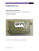
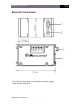
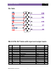
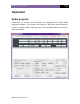
Pin Outs
DB-15 PIN OUT table with input and output levels
D-Type
Pin No.
Function Description Signal Type Input/
Output
1 DCD Data Carrier Detect RS-232 O/P
2 RXD Received Data RS-232 O/P
3 TXD Transmitted Data RS-232 I/P
4 DTR Data Terminal Ready RS-232 I/P
5 GND Ground connection to chassis of the radio. 0V (Chassis)
6 DSR Data Set Ready RS-232 O/P
7 RTS Request To Send RS-232 I/P
8 CTS Clear To Send RS-232 O/P
9 RI Ring Indicator RS-232 O/P
10 AUDIO OUT Discriminated audio output Analog O/P
11 GND Ground connection to chassis of the radio. 0V (Chassis)
12 +12V Power supply input (Nominal 12V) 9.0V – 18.0V DC I/P
13 GND Ground connection to chassis of the radio. 0V (Chassis)
14 AC1 AC IN Analog I/P
15 AC2 AC IN Analog I/P