
Installation Instructions
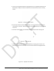
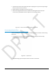
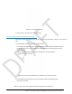


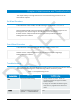
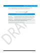

Table Of Contents
- R900 cellular endpoint Wall and Pit Installation and Maintenance Guide
- Contents
- Figures
- Tables
- Chapter 1: Product Description
- Chapter 2: Specifications
- Chapter 3: General Installation Guidelines
- Chapter 4: Wall Installation
- Chapter 5: Pit Installation
- Chapter 6: Maintenance and Troubleshooting
- Appendix A: Endpoint Modes
- Appendix B: Field Manager
- Glossary

30
R900 cellular endpoint Wall and Pit MIU Installation and Maintenance Guide
3.
Take a non-stripped black wire from the pigtail and a non-stripped black wire from the
R900 cellular endpoint and insert the wires into the Scotchlok connector until fully
seated.
Figure 38 – Seating Connector Wires
4.
Do not strip colored insulation from the wires, or strip and twist bare wires prior to
inserting into a connector. Insert the insulated colored wires directly into the Scotchlok
connector.
5.
Place the connector (red cap side down) between the jaws of the crimping tool.
Figure 39 – Crimping Tool
6.
Check to ensure the wires are still fully seated before crimping the connector. The
following image illustrates improper connections due to wires not being fully seated.
Figure 40 – Improper Connections