R900 cellular endpoint Wall and Pit Installation and
Maintenance Guide
R900 cellular endpoint Wall and Pit Installation and Maintenance Guide
Copyright This manual may not be reproduced in whole or part, in any form or by any means, electronic or mechanical, for any purpose, without the express written permission of Neptune Technology Group Inc. All rights to design or inventions disclosed herein, including the right to manufacture, are reserved to Neptune Technology Group Inc. Trademarks Used in This Manual ProRead and E-CODER are trademarks of Neptune Technology Group Inc. R900 is a registered trademark of Neptune Technology Group Inc.
RF Exposure Information This equipment complies with the FCC RF radiation requirements for uncontrolled environments. To maintain compliance with these requirements, the antenna and any radiating elements should be installed to ensure that a minimum separation distance of 20 cm is maintained from the general population. compliance could void the users' authority to operate the equipment. Professional Installation In accordance with section 15.
R900 cellular endpoint Wall and Pit Neptune Technology Group Inc. Installation and Maintenance Guide 1600 Alabama Highway 229 Literature No. IM R900 cellular Tallassee, AL 36078 endpoint 07.20 Part No. Tel: (800) 633-8754 Fax: (334) 283-7293 Copyright © 2021 Firmware © 2021 Neptune Technology Group Inc. Neptune Technology Group Inc. All Rights Reserved. All Rights Reserved.
Contents Chapter 1: Product Description 1 Chapter 2: Specifications 3 Electrical Specifications 3 Transmitter 3 Encoder Register Interface 3 Environmental 4 Functional 4 Dimensions and Weight 4 Chapter 3: General Installation Guidelines Tools and Materials 7 7 Recommended Tools 7 Recommended Materials 8 Safety and Preliminary Checks 8 Verifying and Preparing the Encoder Register 8 Installing a Register (Non Pre-Wired or Potted Only) 9 Chapter 4: Wall Installation 13 Prior to In
Contents Verifying the Meter Reading Chapter 5: Pit Installation 21 23 Prior to Installation 23 Storage 23 Unpacking 23 Tools and Materials 24 Site Selection 24 R900 cellular endpoint Pit Installation 26 Installing the Antenna 26 Begin the Installation 27 Installing the Scotchlok™ Connectors 29 Connecting the Splice Tube 31 Tying the Cable and Activating the R900 cellular endpoint 32 Testing the Installation 33 Chapter 6: Maintenance and Troubleshooting 35 Six Wheel Encoders 35
Figures Figure 1 – R900 cellular endpoint – Wall 1 Figure 2 – R900 cellular endpoint – Pit 1 Figure 3 – R900 cellular endpoint Pit – Dimensions Front and Side 4 Figure 4 – R900 cellular endpoint Wall – Dimensions Front and Side 5 Figure 5 – Wiring a Neptune Encoder Register 10 Figure 6 – Color Code for Wires 10 Figure 7 – Cable Threaded Around Strain Relief Posts 11 Figure 8 – Application of the Sealant 11 Figure 9 – Covering the Terminal Screws 12 Figure 10 – R900 cellular endpoint Back P
Figures Figure 28 – Inserting the Antenna into the Pit Lid 26 Figure 29 – Locking the Nut on the Antenna 26 Figure 30 – Antenna Installation Complete 26 Figure 31 – Removing the Protective Cap 27 Figure 32 – R900 cellular endpoint Conductor Pin 27 Figure 33 – Aligning the Pin 28 Figure 34 – Locking the Antenna into Place 28 Figure 35 – Swiping the endpoint 28 Figure 36 – Scotchlok™ Connector 29 Figure 37 – R900 cellular endpoint Color Code for Wires 29 Figure 38 – Seating Connector Wire
Tables Table 1 – Transmitter Specifications 3 Table 2 – Supported Encoder Maximum Cable Length 3 Table 3 – Environmental Conditions 4 Table 4 – Functional Specifications 4 Table 5 – Recommended Tools 7 Table 6 – Recommended Materials 8 Table 7 – Maximum Cable Lengths 15 Table 8 – Cable Length and Manufacturer 25 Table 9 – Example Reading Values 35 Table 10 – Leak Status Flag Descriptions 37 R900 cellular endpoint Wall and Pit MIU Installation and Maintenance Guide xi
Tables This page intentionally left blank.
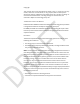
Chapter 1: Product Description This chapter provides a general description of the Neptune® R900 cellular endpoint for wall and pit applications. The R900 cellular endpoint isa network endpoint that collects meter reading data from an encoder register. It then transmits the data for collection using LTE-M cellular technology. The collection data is stored and downloaded into the utility billing system for processing. The R900 cellular endpoint iseasily installed in wall or pit applications.
Figure 3 – R900 cellular endpoint – Pit w/external antenna 2 R900 cellular endpoint Wall and Pit Installation and Maintenance Guide
Chapter 1: Product Description This page intentionally left blank.
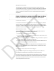
Chapter 2: Specifications This chapter covers the specifications for the R900 cellular endpoint. Electrical Specifications The power is supplied by a lithium battery. Transmitter The following table defines the R900 cellular endpoint transmitter specifications. Table 1 – Transmitter Specifications Description Transmit Period Fifteen-minute readings delivered four times per day. Encoder Reading 15-minute. Output Power Meets FCC Part 15.247 and FCC Part 27. FCC Verification Part 15.247.
Environmental The following table provides the environmental specifications of the R900 cellular endpoint. Table 3 – Environmental Conditions Operating Temperature –22° to 149°F (–30° to 65°C). Storage Temperature –40° to 158°F (–40° to 70°C). Operating Humidity 0 to 100% condensing. Functional The following table provides the functional specifications of the R900 cellular endpoint . Table 4 – Functional Specifications Register Reading Endpoint ID Nine digits.
Chapter 2: Specifications Figure 3 – R900 cellular endpoint Pit w/external antenna – Dimensions Front and Side 4 R900 cellular endpoint Wall and Pit MIU Installation and Maintenance Guide
Chapter 2: Specifications Figure 4 – R900 cellular endpoint Wall – Dimensions Front and Side R900 cellular endpoint Wall and Pit MIU Installation and Maintenance Guide 5
Chapter 2: Specifications This page intentionally left blank.
Chapter 3: General Installation Guidelines This chapter describes tools, materials, and general installation guidelines for the R900 cellular endpoint. Tools and Materials Chapter 3 defines the recommended tools and materials you need to successfully install the R900 cellular endpoint. Some items may not apply to your specific installation, or the list may not contain all required tools or materials.
Chapter 3: General Installation Guidelines Recommended Materials The following table defines the materials recommended to install the R900 cellular endpoint . Table 6 – Recommended Materials Description Use Cable Solid 3 Conductor #22 AWG (black / green / red) (part # 6431-352). Connect the R900 cellular endpoint to encoder Moisture Novagard® sealant (part# 96018-072). Cover exposed wires and terminal Protection Scotchloks Part# 8138-125. Site Work Order Documentation provided by your utility.
Chapter 3: General Installation Guidelines The R900 cellular endpoint also operates with competitor registers using Sensus UI-1203 protocol which includes: Sensus ECRIII ICE iPerl OMNI, and electronic registers Hersey/Mueller Translator Badger ® ADE HR-E LCD Before installing an R900 cellular endpoint,theencoder register must be correctly wired and programmed to work with the R900 cellular endpoint . E-CODER and ProCoder registers do not require programming.
6. Strip off 1/2 inch of insulation from each of the three wires. Figure 5 – Wiring a Neptune Encoder Register 7. If required, connect the three conductor wires to the encoder register's terminal per the manufacturer's instructions.
8. Thread the cable around the strain relief posts of the encoder. Figure 7 – Cable Threaded Around Strain Relief Posts 9. Apply sealant liberally and ensure that it encapsulates the terminal screws and exposed wires. Neptune requires Novagard® G661 sealant or Dow® compound 4.
10. Snap the cover onto the encoder register. Figure 9 – Covering the Terminal Screws 11. Run the cable to the R900 cellular endpoint and fasten it securely. Do not exceed maximum cable lengths as defined in "Encoder Register Interface" on page 3. If the encoder register is prewired and potted, use Schotchloks for connecting the register to the R900 cellular endpoint.
Chapter 4: Wall Installation This chapter describes storage and unpacking instructions, preliminary tests, tools, materials, site selection, and the wall installation procedure for the R900 cellular endpoint. Prior to Installation Any existing network registers must be reprogrammed. The R900 cellular endpoint does not have networking capability Storage After receipt, inspect the shipping containers for damage, and inspect the contents for damage prior to storage.
Chapter 4: Wall Installation Figure 10 – R900 cellular endpoint Back Plate Figure 11 – R900 cellular endpoint Wall Kit Tools and Materials "Tools and Materials" on page 7 shows the recommended tools and materials you need to successfully install the R900 cellular endpoint. Some items may not apply to your specific installation, or the list does not contain all required tools or materials. Site Selection R900 cellular endpoint.
Chapter 4: Wall Installation Clear the selected location of all obstructions. Avoid installing the R900 cellular endpoint behind metal fences or walls. The maximum cable length between the encoder register and R900 cellular endpoint depends on the register's manufacturer and model. See the following table for the maximum cable lengths. Table 7 – Maximum Cable Lengths Encoder Register Neptune ARB® V. Meets manufacturer's published specification for wire length to the encoder. 300 feet (91 meters).
Chapter 4: Wall Installation The Hi-Lo fastener for securing the main R900 cellular endpoint housing to the adapter plate is shipped separately. 2. Study "Site Selection" on page 14 and then decide how to install the R900 cellular endpoint. You can insert the cable through any of the entry holes in the back of the mounting adapter. A variety of holes allows for a quick and easy installation.
Chapter 4: Wall Installation 2. Pair the wires according to the color diagram. Figure 15 – Color Code for Wires 3. Slide the paired wires into the grooves provided until they seat into the back of the gel cap. 4. Squeeze the gel cap firmly using the appropriate crimping tool to ensure a good connection. 5. Repeat this process until all connections are complete. 6. Store excess wire and Scotchloks in the hollow cavity in the back of the R900 cellular endpoint using the strain relief guides.
Chapter 4: Wall Installation 7. Continue to guide the remaining wire through the cable exit notch at the bottom right side of the R900 cellular endpoint. Figure 17 – Cable Exit Notch Completing and Testing the Installation Follow this procedure to complete and test the installation. 1. Slide the tongue on the top of the R900 cellular endpoint into the groove on the top of the mounting adapter. 2. Secure the R900 cellular endpoint to the mounting adapter using the set screw.
Chapter 4: Wall Installation 3. Position the magnet against the left side of the R900 cellular endpoint directly in line with the Neptune logo. 4. Move the magnet up and over the top left corner of the R900 cellular endpoint. Figure 19 – Swiping the R900 cellular endpoint 5. Install a seal wire or seal clip through the seal hole at the bottom of the R900 cellular endpoint main housing. Figure 24 – Installing the Seal Wire 6.
Chapter 4: Wall Installation Testing the Installation The Neptune360FieldManager App can be used to verify cellular connectivity and meter reading to ensure that the R900 cellular endpoint is installed correctly. < Image Placeholder> Figure 20 – CMIU™ Manager Options To test the installation, complete the following steps. First, be sure to swipe the R900 Cellular Endpoint with a magnet. For more information, see "Completing and Testing the Installation" on the previous page. 8.
Chapter 4: Wall Installation If the signal strength displayed is Excellent or Good, the cellular coverage is adequate. If the signal strength is Fair, or Poor, cellular connectivity may be impacted. 12. Verify that the meter reading is valid. If the meter reading is: • Valid, continue with the next step. • Invalid, verify all endpoint to register connections and test the installation again.
20 R900 cellular endpoint Wall and Pit MIU Installation and Maintenance Guide
R900 cellular endpoint Wall and Pit MIU Installation and Maintenance Guide 21
This page intentionally left blank.
Chapter 5: Pit Installation This chapter describes storage and unpacking instructions, preliminary tests, tools, materials, site selection, and pit installation of the R900 cellular endpoint. Prior to Installation Follow the procedures in this section before you install the R900 cellular endpoint. Storage After receiving the shipment, inspect the containers for damage and inspect the contents for damage prior to storage. After completing the inspection, store the cartons in a clean, dry environment.
Chapter 5: Pit Installation Tools and Materials See Chapter 3, General Installation Guidelines, for the recommended tools and materials you need to successfully install the R900 cellular endpoint. Some items may not apply to your specific installation, or the list may not contain all required tools or materials. Site Selection Installation and operation in moderate temperatures increase reliability and product life. For more information, see "Environmental" on page 4.
Chapter 5: Pit Installation Figure 27 – R900 cellular endpoint - Pit w/Internal Antenna Clearances • For Pit endpoints with the internal antenna, the meter pit must use a plastic polymer lid. Pits with metal lids require the pit endpoint with external antenna. • • Make sure the pit location gives adequate room for installing both the R900 cellular endpoint and the flange or TTL pit antenna (if used).
Chapter 5: Pit Installation Figure 26 –Flange or Antenna Placement for Low Traffic Areas • When installing in a high traffic area, Neptune recommends that the dome of the flange or pit antenna be recessed in the pit lid as shown in the following • figure. Recessing the installation reduces the range of the pit antenna.
Chapter 5: Pit Installation R900 cellular endpoint Pit Installation The following section describes how to install a single R900 cellular endpoint in a pit location. The Pit endpoint can be purchased in two formfactors: • R900 cellular endpoint pit w/internal antenna • R900 cellular endpoint pit w/external antenna Be sure to select the appropriate version based on the recommendations in “Site Selection” on page 24.
Chapter 5: Pit Installation 6. Slide the endpoint housing onto flange tube with the face of the endpoint housing toward the pit lid until the face of the endpoint is touching the underside of the lid. 7. Thread the locking nut onto the flange tube, with the unthreaded end toward the lid until it is loosely touching the endpoint housing. 8. Rotate the endpoint horizontally as needed to fit into the meter pit and finish tightening the locking not to secure the endpoint in place.
Chapter 5: Pit Installation 9. Put the meter pit lid back in place ensuring a snug fit with the meter pit. Pit endpoint w/External TTL Antenna Installation Complete these steps to install the endpoint w/external antenna in a pit. 1. Insert the antenna cable and housing through the 1-3/4 inch hole in the meter pit lid.
Chapter 5: Pit Installation Figure 28 – Inserting the Antenna into the Pit Lid 2. Thread the locking nut onto the antenna, with the unthreaded end toward the lid. Figure 29 – Locking the Nut on the Antenna Figure 30 – Antenna Installation Complete 3.
Chapter 5: Pit Installation Figure 32 – R900 cellular endpoint Conductor Pin 6. When the pin is properly aligned, push the antenna connection down fully onto the connection of the endpoint, so that the latch plate is engaged on all three posts. Figure 33 – Aligning the Pin 7. Turn the antenna clockwise until it locks into place. Figure 34 – Locking the Antenna into Place 8.
Chapter 5: Pit Installation 9. Once the register and antenna are connected the R900 cellular endpoint can be activated. Using a magnet, swipe clockwise around the top left corner of the endpoint, starting halfway down the long side of the endpoint and finishing at the middle of the shorter side to activate the endpoint.
Chapter 5: Pit Installation Installing the Scotchlok™ Connectors Complete the following steps to install the Scotchlok™ connectors. Make sure you complete the pit installation procedures before you install the Scotchloks. 1. Use the 3M Scotchlok-type connector to connect the R900 cellular endpoint wires to the encoder wires. 2. Hold the Scotchlok's connector between the index finger and thumb with the red cap facing down.
3. Take a non-stripped black wire from the pigtail and a non-stripped black wire from the R900 cellular endpoint and insert the wires into the Scotchlok connector until fully seated. Figure 38 – Seating Connector Wires 4. Do not strip colored insulation from the wires, or strip and twist bare wires prior to inserting into a connector. Insert the insulated colored wires directly into the Scotchlok connector. 5. Place the connector (red cap side down) between the jaws of the crimping tool.
7. Squeeze the connector firmly with the proper crimping tool until you hear a pop and gel leaks out the end of the connector. 8. Repeat steps two through six for each color wire. 9. After connecting all three color wires, read the encoder register to ensure proper connections, and the R900 cellular endpoint is functioning properly.
Figure 43 – Gray Wires in Slots 3. Snap the cover closed to finish the installation. Securing the Endpoint to the Antenna Tube Follow this procedure in deep pits or vaults to secure the R900 cellular endpoint to the Antenna Tube 1. Place the R900 cellular endpoint in the pit location: In a shallow pit application, you can place the R900 cellular endpoint beside the meter. In deep pit applications, use a cable tie to suspend the R900 cellular endpoint from the antenna shaft.
Testing the Installation To test the installation, follow the steps in "Testing the Installation" on page 20.
This page intentionally left blank.
Chapter 6: Maintenance and Troubleshooting This chapter takes you through maintenance and troubleshooting procedures for the R900 cellular endpoint. Six Wheel Encoders If the odometer reads 123456, the CMIU Manager should show 1 2 3 4 5 5 0 0. The sixth digit displayed is a five, if the last digit on the odometer is five through nine. The sixth digit is a zero, if the last digit on the odometer is zero through four.
Chapter 6: Maintenance and Troubleshooting Contact Information Within North America, Neptune Customer Support is available Monday through Friday, 7:00 A.M. to 5:00 P.M. Central Time, by telephone or email. By Phone To contact Neptune Customer Support by phone, complete the following steps. 1. Call (800) 647-4832. 2. Select one of the following options: 1 if you have a Technical Support Personal Identification Number (PIN). 2 if you do not have a Technical Support PIN. 3.
Appendix A: Endpoint Modes There is a single mode of operation for the R900 cellular endpoint, which provides 15-minute register interrogations with readings delivered every six hours. Table 10 – Leak Status Flag Descriptions Leak Status Flag (Resets After 35 Days) Based on total amount of 15-minute periods recorded in the previous 24-hour period. Leak icon off Eighth digit incremented less than 50 of the 96 days of 15-minute intervals.
Appendix A: endpoint Modes This page intentionally left blank.
Appendix B: Field Manager Field Manager is an Android and iOS application that can communicate with a cellular endpoint during the installation, troubleshooting, and maintenance of the MIU. The MIU Manager provides the following functionality checks on the MIU: • LTE Connection Status The Manager is compatible with iOS version X.X and Android Y using either an iPhone or iPad.
Screen 38 R900 cellular endpoint Wall and Pit MIU Installation and Maintenance Guide
Appendix B: CMIU Manager R900 cellular endpoint Wall and Pit MIU Installation and Maintenance 41
Glossary A antenna (pit) Endpoint antenna used for pit installations. AWG American Wire Gauge. C CMIU™ Cellular Meter Interface Unit. F FCC Federal Communications Commission. L Liquid Crystal Display (LCD) Component where the meter-reading and value-added icons are displayed. M MIU Meter Interface Unit.
Glossary R register read time The default time is 15 minutes for all registers. Custom time is not available. S seal pin Small, black plastic nail used to secure the E-CODER®)R900i to the meter. serial number Unique identification number given to each endpoint at the factory. The default value is the last programmed, plus one. Custom serial numbers are not available. T TDI Transport Driver Interface format. transmission time The time between endpoint transmissions.
Index encoders A four wheel 35 American Wire Gauge 9 six wheel 35 AWG 9 I B iOS 19 backflow 37 M battery 3, 13, 23 magnet 7, 19 C maintenance 23 cable 3, 8, 15 mounting adapter 18 22 AWG 3, 9 maximum length 3 three-conductor 9 CMIU™ 15 installing 15 manager 19 testing 19 conductor wire 10 customer support 36 N Novagard® sealant 11 O operating humidity 4 P prewired 12 procedures maintenance 35 D dimensions 4 Dow® Corning 11 troubleshooting 35 ProRead™ 3 R E read E-CODER®)R900i 13 E-C
44 R900 cellular endpoint Wall and Pit MIU Installation and Maintenance Guide
Index receptacle 16 register install 9 potted only 9 S Scotchlok™ 8, 29 seal clip 21 hole 21 sealant 11 storage 13 strain relief posts 11 T TDI 9 temperature operating 4 storage 4, 13 testing the installation 23 tool kit 7 tools 13 Transport Driver Interface format 9 W weight 4 44 R900 cellular endpoint Wall and Pit MIU Installation and Maintenance Guide