
User's Manual


Model: R900-v3 Advanced Compliance Solutions FCC ID: P2SNTGSRFV3
Warning:
To avoid RF signal saturation of the HHU, position the receiver at least 2 to 3 feet from
the MIU.
When the MIU is installed correctly, its MIU ID and a meter-reading will appear on the HHU’s display
within one minute. Verify that this is the correct meter reading by comparing it to the meter’s dial.
If a meter-reading does not appear on the HHU’s display or the meter reading in the HHU’s display is not
the same as the reading on the meter’s dial:
Reactivate the MIU using the magnet.
Verify all electrical connections.
Test the installation again (repeat above steps).
If a ProRead Encoder Register is used:
Insure the unit is programmed in “3-wire mode”.
Verify all electrical connections.
Reactivate the MIU using the magnet
If a problem still exists contact your Neptune representative.
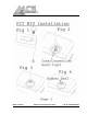
PIT MIU Installation
Note: Before wiring the encoder register, make sure the cable is long enough so that
when the installation is complete, the pit lid (with MIU attached) can be removed easily
without straining the cable.
1. Feed the antenna cable and housing through the 1 ¾” hole in the meter pit lid. Slip the large plastic
nut over the antenna cable and thread it onto the antenna assembly to secure it to the pit lid (Figure
1).
2. Connect the coaxial cable connector to the connector on the transmitter housing (Figure 2).
3. Making sure the washer is properly seated, connect the plastic connector housing to the 3-lobed
black plastic latch-plate
(Figure 3).
4. Slide the black conical-shaped gasket down the cable until it engages the connector housing (Figure
4).
5. Tighten the connector nut onto the threaded portion of the connector housing (Figure 5).
6. If desired, use the included cable tie to hang the MIU from the antenna tube (Figure 6).
7. Place the magnet against the side of the MIU in the area shown and swipe it in the indicated direction
to activate the MIU
(Figure 7).
Wall MIU Installation
Gel caps should be used to connect the pigtail from the MIU to the register wire.
When using the Scotchlok gel caps, pair the wires according to the color chart in Table 1. With the
ends of the colored wires stripped approximately ¼”, slide the pair into the gel cap as far as they will go.
Then, firmly squeeze the gel cap with an appropriate crimping tool. One gel cap should be used for each
colored wire pair.