
User's Manual
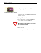

Table Of Contents

R900 Wall and Pit Installation and Maintenance Guide I-1
Index
Numerics
3-conductor 33
3-conductor wire 8
3-wire connector cable 20
3-wire mode 7, 8, 21, 28
A
algorithm, RF frequency control 2
antenna 12
cable 14, 15
care 30
dome 12
F connector 15
flange 12
locking nut 14
part # 33
recessing 12
remove from handheld 21, 27
shaft 16
B
Battery
replace
30
battery
assembly
33
casing 31, 32
compartment 30
connection 31
internal 6, 11, 12, 22, 30
lithium 3
low, RF emission 2
main housing 32
new 31
remove 30
remove casing 30
replace 29
replacing 30
wires 31
C
cable 6
3-conductor 8
3-wire connector 20
additional 13
antenna 14, 15
attached to MIU 13
connector 15
exit 26
lengths 3, 10, 13, 23, 24
rear entry 25
strain relief post 26
strain relief posts 9
threaded 9
ties 16
channel frequency 3
compound units 2
connect
3-conductor cable
8
3-conductor wire 8
cable 8
encoder register 8
MIU 6, 8
connector housing 15
control, algorithm for RF frequency 2
D
description, R901 2
dimensions 4, 5
E
electrical specifications 3
Encoder register
illustrated
8
interface 3
maximum cable length 3
Environmental conditions 4, 5
F
F connector 14, 15
flange, pit antenna 12
Functional specifications 4, 5
G
gel caps 25, 26, 31
H
handheld
check system setup
29
power up 21, 27
reading 3
walkby 1
HHU 21, 27
I
Installation
preliminary checks
7
safety 7
site selection 12, 23
guidelines 12, 23
tools 23