
User's Manual
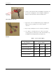
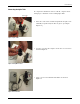
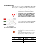
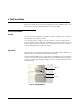
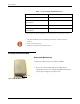
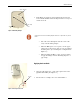
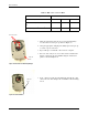
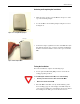
Table Of Contents
Wall Installation
26 R900 Wall and Pit MIU Installation and Maintenance Guide
3 Slide the paired wires into the grooves provided until they
seat into the back of the gel cap. Refer to
Figure 35.
4 Using an appropriate crimping tool, firmly squeeze the gel cap
to ensure a good connection.
5 Repeat this process until all connections are complete.
6 For rear cable entry, store excess wire and Scotchloks in the
hollow cavity in the back of the MIU using the strain relief
guides as shown in
Figure 34.
Figure 34 Cable in Back of Mounting Adapter
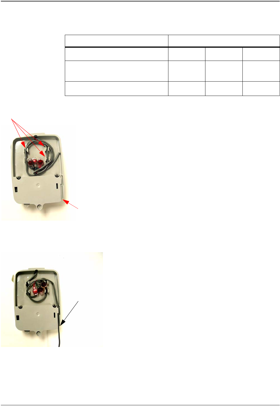
7 Next, continue to guide the remaining wire through the cable
exit notch at the bottom right side of the MIU as shown in
Fig-
ure 34.
Figure 35 Cable Exit Notch
Table 7 MIU Color Code for Wires
Encoder Register MIU Wire Color/ Encoder Terminal Marking
Neptune ARB III, IV and V Black / B Green / G Red / R
Neptune ProRead (ARB V) and E-Coder (ARB
VII)
Black / B Green / G Red / R
Sensus (Invensys) ECRII
®
and ECRIII
®
Black / R Green / B Red / G
strain relief guide
cable exit
notch
cable exit
notch