
User's Manual
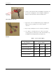
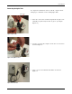
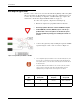
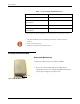
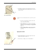
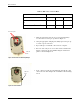
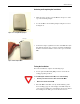
Table Of Contents
Pit Installation
18 R900 Wall and Pit MIU Installation and Maintenance Guide
6 Check to ensure that the wires are still fully seated in the con-
nector before crimping the connector. Figure 24 illustrates
improper connections due to wires not fully seated.
Figure 24 Improper Connections
7 Squeeze the connector firmly with the proper crimping tool
until you hear a pop and gel oozes out the end of the
connector.
8 Repeat steps 2 through 6 for each color wire. (See Table 5.)
9 Once all three color wires have been connected, read the
encoder register to ensure proper connections and the recep
-
tacle/MIU is functioning properly. (See Figure 25.)
Figure 25 Three Color Wires
Connected
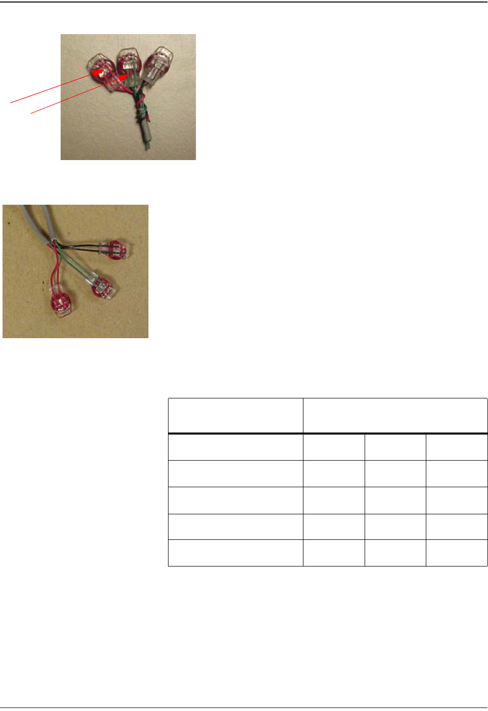
Table 5 Color Code for Wires
Red and
Green Wires
-- not fully
seated
Approved
Encoder Register
MIU Wire Color/
Encoder Terminal
Neptune ARB
®
V
Black / B Green / G Red / R
Neptune ProRead (ARB
®
VI)
Black / B Green / G Red / R
Neptune E-Coder (ARB
®
VII)
Black / B Green / G Red / R
Sensus (Invensys) ECR II Black / R Green / B Red / G
Sensus (Invensys) ECR III Black / R Green / B Red / G