
Maintenance Guide
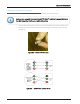
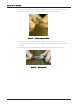
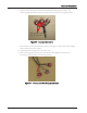
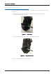
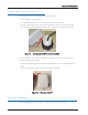
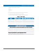
Table Of Contents

3. Take a non-stripped black wire from the pigtail and a non-stripped black wire from the
CMIU and insert the wires into the Scotchlok connector until fully seated.
Figure 37 – Seating Connector Wires
4. Do not strip colored insulation from the wires, or strip and twist bare wires prior to
inserting into a connector. Insert the insulated colored wires directly into the Scotchlok
connector.
5. Place the connector (red cap side down) between the jaws of the crimping tool.
Figure 38 – Crimping Tool
30 Cellular MIU (CMIU™) Pit and Wall Installation and Maintenance Guide
Chapter 5: Pit Installation