
User Manual

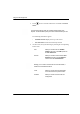


Table Of Contents
- 14-0066 - Exhibit Cover.pdf
- PUBLICATION_UM Handheld_12.13.pdf
- Neptune Handheld System User’s Manual
- 1 Introduction
- 2 Overview of the Neptune Handheld System
- 3 Using the CE5320 Handheld
- 4 Using the Nomad Handheld
- 5 Setting Up the R900 Belt Clip Receiver
- R900 Belt Clip Receiver
- Nomad Handheld and R900 Belt Clip Receiver
- Unpacking and Inspecting Equipment
- Using the R900 Belt Clip Receiver
- Using the R900 Belt Clip Receiver to Read a Route
- Updating R900 Belt Clip Receiver Firmware
- 6 Gathering Route Data
- The Reading Entry Screen
- Manually Collecting Meter Readings
- Collecting RR Readings
- Working with Accounts
- Validating Readings
- Removing a Reading
- Clearing a Skip Code
- Clearing a Comment Code, Customer Note, or Trouble Code
- Adding a New Meter to a Route
- Correcting or Changing Meter Information
- Finding and Displaying Reading-Entry Screens
- Resequencing Routes
- 7 Communicating with the Host Computer
- 8 Using the Field Programmer
- Connecting the Mouse
- Starting Field Programmer
- Programming the ProRead
- Querying the ProRead
- Reading the ProRead Register
- Programming the R900G Endpoint
- Using Command Gas
- Reading the R900G Endpoint Register
- Networking Two Registers
- Managing Formats
- 9 Maintaining and Repairing the Neptune Handheld System
- 10 Troubleshooting
- Appendix A Changing Volume Settings
- Appendix B Tokens List for Custom Format Screen
- Appendix C Pressure Configuration Factor Indexes
- Glossary
- Index
- Neptune Locations

Using the Field Programmer
Notes:
8-44 N_SIGHT R900 User’s Manual for the Neptune Handheld System
After you select a
format, all the values
ass
ociated with it appear
as shown in Figure 8.40.
You can then make any
necessary changes.
Figure 8.40 Gas Values Shown on
New Format Screen
5 Touch or click in MULTIPLIER to select the correct value
from 0.01 to 1000 to be use for the format.
6 Type a value for INPUT to
enter the input rate. This is controlled
by the index.
7 Type the 9-digit number for the Pressure Con
figuration Factor
index in PCF.
Refer to the listing of PCF indexes, refer to “Pressure Configuration
Factor Indexes,” in Appendix C.These are examples only
. This list
does not include every index a utility has
in its system. If there are
any questions about the correct pressure configuration factor,
contact the meter manufacturer.
8 Touch in DispDig
its to select one of the following:
• 4 = Initial Reading will be in range of 0000 - 9999
• 5 = Initial Reading will be in range of 00000 - 99999
• 6 = Initial Reading will be in range of 000000 - 999999