
Instruction Manual

NEMCO FOOD EQUIPMENT 301 Meuse Argonne, Hicksville, OH 43526
1-800-782-6761 Toll Free 419-542-6690 Fax
www.nemcofoodequip.com 49206
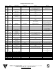
7
Item #
Nemco
P/N
Description
(Location)
Component
Rating
How to
Check
Special
Notes
1
47420
Rocker Switch
(Control Panel)
15A, 125vac
Check for continuity between the upper and
lower terminals on both sides
independently.
Install with the terminals to the
bottom of the unit.
2
48708
Element, Top
(Upper Deck)
500W, 120VAC
Check for continuity terminal to terminal.
Resistance should be approximately 28
ohms.
3
48709
Element, Side
(Right Upright)
750W, 120VAC
Check for continuity terminal to terminal.
Resistance should be approximately 19
ohms.
4
48710
Element, Water Tank
(Water Tank Housing
Assembly)
400W, 120VAC
Check for continuity terminal to terminal.
Resistance should be approximately 36
ohms.
5
47207-1
Foil Heater
(Bottom Deck)
20W, 120VAC
Check for continuity terminal to terminal.
Resistance should be approximately 720
ohms.
6
47370-1
Ballast
0.5A, 120VAC
Check for voltage between the red and blue
wire on the ballast.
Install with the line and neutral
wires to the front of the unit.
Keep the red and blue wires
from the ballast away the relay.
7
48705
Flash Relay
(Bottom Deck)
1A, 115VAC
Empty the water tans.
Verify continuity in the liquid level switch.
Check voltage across terminals #1 & #4
Install with the terminal facing
the center of the unit.
Keep the red and blue wires
from the ballast away the relay.
8
48707-1
Fan, Dampener
0.185A, 115VAC
Verify air flow.
Install with the air flowing up into
the upright.
Do not over tighten.
9
48706
Fan, Top Assembly
(Bottom Deck)
12W, 115VAC
Verify air flow.
Installed with the air flowing
down into the cabinet.
10
47397-1
Fan, Water Tank
(Water Tank Housing
Assembly)
0.18A, 115VAC
Verify air flow.
Install with the air flowing across
the water tank.
11
48703
Control Board
(Control Panel)
N/A
Verify the control board is properly
controlling the setting by adjusting the
setting.
12
48704
Sensor, RH / Temp
(Left Upright)
N/A
Control board will display “Err1”
Check connection between
sensor and board prior to
replacing when display “Err1”
13
80482
Power Supply
(Bottom Deck)
120VAC
Check for voltage on both the rear and front
output with the control board calling for
heat.
Install with the terminal to the
center of the unit.
14
47876-1
Liquid Level Switch
(Water Tank Housing
Assembly)
0.08A, 120VAC
Check for continuity terminal to terminal
with the switch both opened and closed.
Do not over tighten the float
switch as it will damage it.
NS
47876-3
Liquid Level Switch (3
Pack)
15
48711
Fluorescent Bulb
(Upper Deck)
14W
Verify voltage from ballast in socket.
Only replace with shatter
resistant bulb.
16
45380-1
Indicator Light, Red
(Control Panel / Rear
Panel)
1/2W, 120VAC
Empty water tank. If it does not illuminate,
check Flash Relay and bottom Liquid Level
Switch.
17
45380-2
Indicator Light, Green
(Control Panel / Rear
Panel)
1/2W, VAC
Fill water tank. If it does not illuminate,
check the top Liquid Level Switch
18
48317-B
Silicone Tubing, ¾”ID
Fill Tank to Secondary Tank –
17”
Secondary Tank to Main Tank –
11”
19
48319-B
Silicone Tubing, 5/16”ID
60”
20
48323
Elbow, 3/8” to 3/8”
Connected directly to main tank.
21
48320
Barbed Fitting, Male
Connected to drain valve.
22
48321
Barbed Fitting, Female
Connect to 48323 Elbow
23
48322
Hose Clamp, Drain
Located on drain tube.
24
48764
Hose Clamp
Located in inside unit.
25
48310
Drain Valve
Located on drain tube.
26
48765
Front Door Dampener
Located on Front Doors.
NS
69426
Bottom Panel Kit
NS
69425
Water Tank Guard
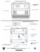
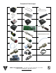
Component Parts List