
Instruction Manual


Chapter 4: System Design and Installation Pointe Controller User Guide
94
OL2304 4 channel voltage output, 0-5V, 0-10V, +/-5V, +/-10V
OL2408 8 channel 0-5VDC or 0-10VDC in
OL2418 8 channel 4-20mA in
Communications
OL2602 2 Port RS232
4.7.2 Available Operator Panels
The following is a list of currently available OptiLogic Operator Panels:
Pushbutton / Indicator Panels
OL3406 6 Indicator/4 Pushbutton Alphanumeric Display
OL3440 4 Line x 20 Character backlit LCD alphanumeric display
Terminal Panels
OL3420 2 Line x 20 character backlit LCD display, 4 pushbuttons
OL3850 2 line x 20 character backlit LCD display, 5 user definable pushbuttons,
numeric keypad, 3 indicator light bars
4.7.3 Calculating Your Power Budget
Each I/O module and operator panel that you install in your Pointe Controller unit
requires a certain minimum amount of power to operate. Each controller base
has a maximum of 2.8 A (2800 mA) total power available.
To calculate the power budget for your Pointe Controller, simply add up the
power required for all of the I/O modules and operator panels that you want to
install in the controller. If the total power required is less than or equal to 2.8 A,
then the controller will be able to power everything. If the total power required
is greater than 2.8 A, then you must redesign your application to use a different
combination of modules.
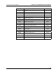
The table below provides a quick reference to the power requirements for all of
the available I/O modules and operator panels. Again, for complete technical
descriptions of these components, see Appendix A, “OptiLogic Technical
Specifications,” starting on page 231.
Module Type Description Power Req.
OL2104 Relay Output, 4-point 250 mA
OL2108 Relay Output, 8-point 375 mA
OL2109 DC Sinking Output, 8-point 140 mA