
Instruction Manual

Pointe Controller User Guide Appendix C: Ladder Diagram Block Reference
399
C.5.7 Rotate bits Left (ROL)
When used in a Ladder Diagram, the ROL block rotates the bits of the input a
specified number of places to the left and sends the result to output.
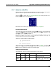
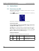
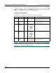
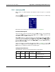
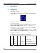
Select the tool (from the Logical and Bit Shift Blocks toolbar) and click on a
ladder rung to insert the following block:
Once the block is inserted, you can double-click on it to configure it.
Functional Description
This block always passes the Enable input state (EN) through to the Enable Out
output state (ENO) without change; when EN becomes on, ENO is turned on, and
when EN becomes off, ENO is turned off.
When EN becomes on, the block function is executed: the Input Value (IN) is rotated the specified
Number of Places (N) to the left. The bits rotated off the left are added back on the right. The
resulting bit pattern is placed in the Output Value (OUT).
Therefore, a 16-bit example of ROL would be:
IN: 1010010101011101
N: 5
OUT: 1010101110110100
The block function is executed every time the ladder is scanned, so long as EN
remains on. If EN becomes off, then OUT remains at its last calculated value until
EN becomes on and the block function is executed again.
Configuration Reference
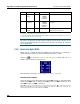
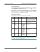
The parameters of this block are described in the following table:
Param Name Config Var Type Description
EN Enable no - The state of the rung (off/on)
received from the left.
ENO Enable
Out
no - The state of the rung (off/on)
passed to the right.