
Instruction Manual


Pointe Controller User Guide Appendix C: Ladder Diagram Block Reference
389
C.5 Logical and Bit Shift Blocks
C.5.1 And (AND)
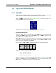
When used in a Ladder Diagram, the AND function block performs a bit-for-bit
“and comparison between two inputs and sends the result to output.
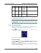
Select the tool (from the Logical and Bit Shift Blocks toolbar) and click on a
ladder rung to insert the following block:
Once the block is inserted, you can double-click on it to configure it.
Functional Description
This block always passes the Enable input state (EN) through to the Enable Out
output state (ENO) without change; when EN becomes on, ENO is turned on, and
when EN becomes off, ENO is turned off.
When EN becomes on, the block function is executed: a bit-for-bit logical
comparison is made between the Input Values 1 and 2 (IN1 and IN2) and the
result is placed in the Output Value (OUT).
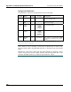
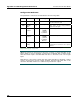
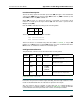
Each set of bits in IN1 and IN2 is evaluated according to the following table:
IN1 0101
IN2 0011
OUT 0001
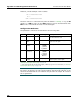
Therefore, a 16-bit example of AND would be:
IN1: 1010010101011101
IN2: 0101011010101110
OUT: 0000010000001100
The block function is executed every time the ladder is scanned, so long as EN
remains on. If EN becomes off, then OUT remains at its last calculated value until
EN becomes on and the block function is executed again.